Control signal / Humidity sensor signal
Theconnectionofanexternalactivecontroller“A1”,apassivecontroller“A2”,anOn/OffHumidistat
“A3”orahumiditysensor(forcontrolviatheinternalcontroller),isaccomplishedontheappropriate
contactsontheterminalstripinaccordancewiththeconnectionschematic.Notethefollowingcon-
nection information:
External
controller
Internal
controller
Connection
active
controller “A1”
passive
controller “A2”
On/Off
controller “A3”
Humidity
sensor
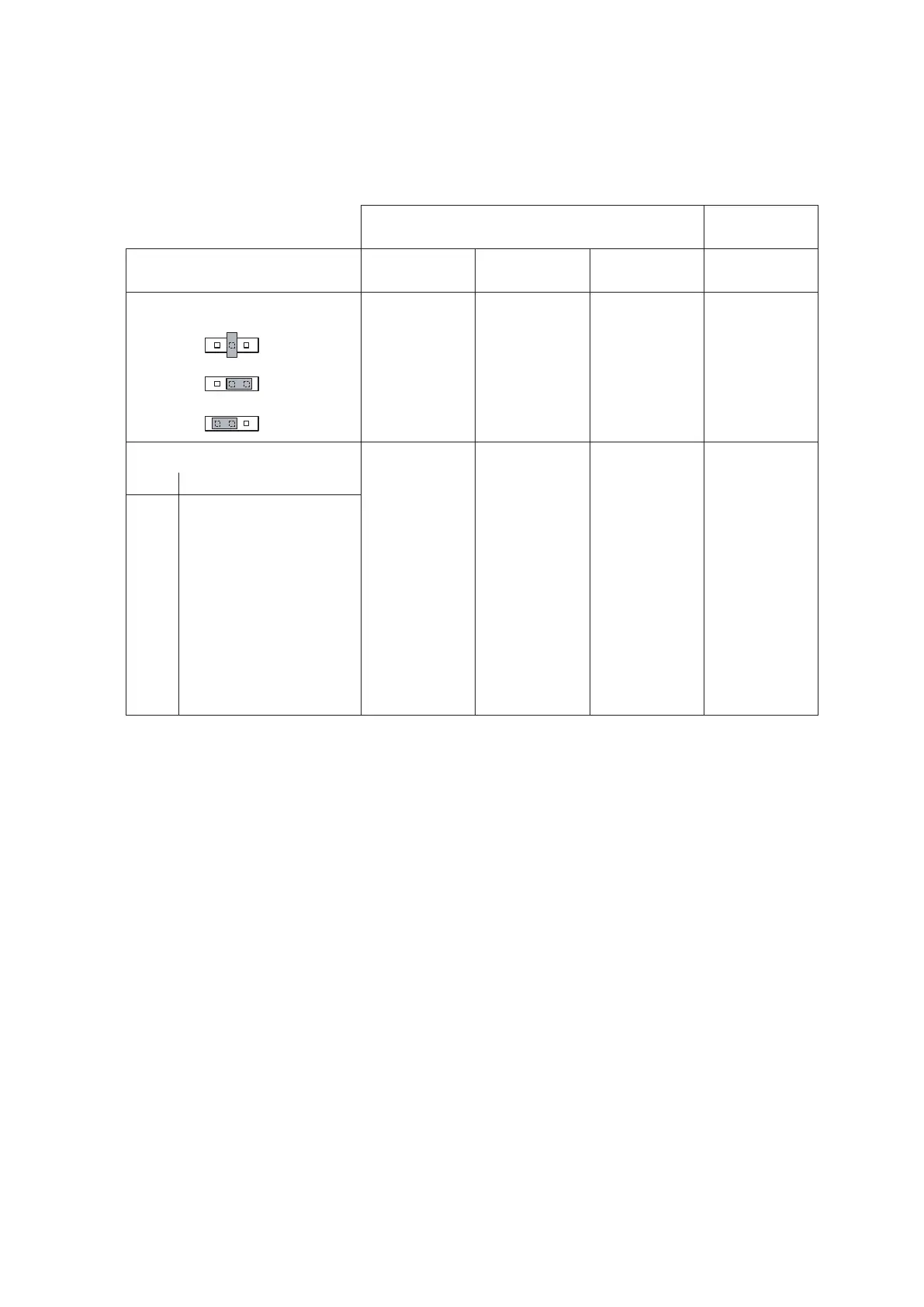
Pos. Jumper JP2
– neutral X X
– 5 V 140Ω...10kΩ
– 24 V X
Rotary switch S3
Pos. Signal
0 No signal selected
1 On/Off24V X
2 0...5 V DC (Potentiometer) X
3 0...10 V DC X X
4 0...1 V DC X X
5 1...5 V DC X X
6 2...10 V DC X X
7 0...20 V Phase intersect X X
8 4...20 mA X X
9 0...20 mA X X
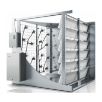
Note: The controller humidity sensor is to be mounted at a suitable position in the duct after the steam
distributionpipe,withaminimumseparationof5timesthehumidicationdistanceB
N
(but not close to
theheatingorcoolingunitsoftheventilationsystem).
Please refer to the separate installation instructions for the controller/sensor when positioning and
connecting these components.
Control cable for versions with two units
Thesuppliedcontrolcable(atribboncable)isconnectedtoterminal“J6”onthecontrolboardofunitA
andtoterminal“J7”onthesupplymoduleofunitB.
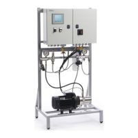
Connecting the fan unit
See separate documentation “Fan unit”.
RS232/RS485 connection
Seeseparatedocumentation“InterfaceRS232/485”