Menu 9
Parameter
structure
Keypad and
display
Parameter x.00
Parameter description
format
Advanced parameter
descriptions
Serial comms
protocol
Performance
128 Mentor MP Advanced User Guide
www.controltechniques.com Issue Number: 4
The binary sum output is given by:
Offset + ones input + (2 x twos input) + (4 x fours input)
The value written to the destination parameter is defined as follows:
If destination parameter maximum ≤ (7 + Offset):
Destination parameter = Binary sum output
If destination parameter maximum > (7 + Offset):
Destination parameter = Destination parameter maximum x Binary sum output / (7 + Offset)
This parameter allows up and down buttons to be disabled under a defined condition, e.g. when the drive is in current limit.
When this is set to 1, the condition to disable the up and down buttons is inverted.
AND
The output is the logic AND of the 2 inputs.
OR
The output is the logic OR of the 2 inputs.
Exclusive OR
The output is the exclusive OR of the 2 inputs.
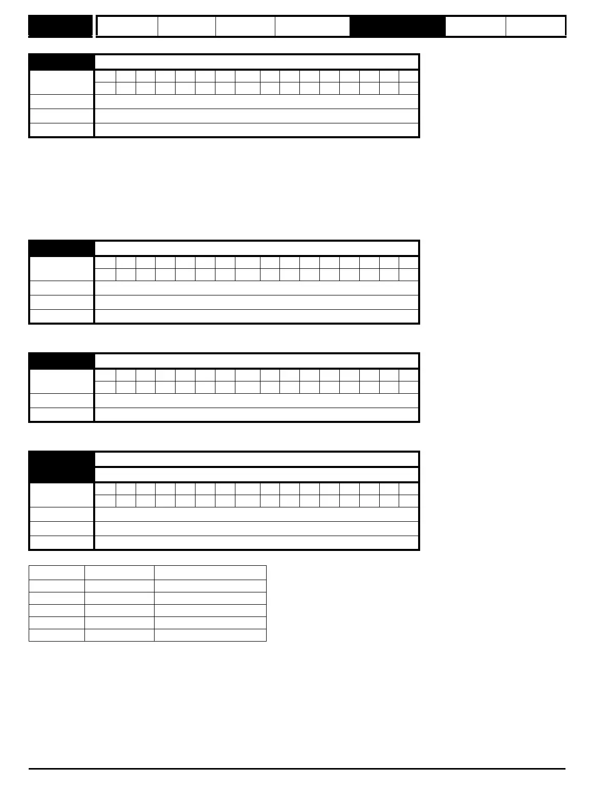
9.34 Binary sum offset
Coding
Bit SP FI DE Txt VM DP ND RA NC NV PT US RW BU PS
1 2 1111
Range 0 to 248
Default 0
Update rate 4 ms read
9.35 Up down disable source
Coding
Bit SP FI DE Txt VM DP ND RA NC NV PT US RW BU PS
2 1111
Range Pr 0.00 to Pr 22.99
Default Pr 0.00
Update rate Read on reset
9.36 Up down disable invert
Coding
Bit SP FI DE Txt VM DP ND RA NC NV PT US RW BU PS
111
Default 0
Update rate 4 ms read
9.37 Logic block 1 mode
9.38 Logic block 2 mode
Coding
Bit SP FI DE Txt VM DP ND RA NC NV PT US RW BU PS
111
Range 0 to 4
Default 0
Update rate 4 ms read
Mode value Action Result
0 AND Output = input1 AND input2
1 OR Output = input1 OR input2
2 XOr Output = input1 XOR input2
3 RS flip flop Input1 – set input2 – reset
4 D type flip flop Input1 – data input2 - clock