Parameter
structure
Keypad and
display
Parameter x.00
Parameter description
format
Advanced parameter
descriptions
Serial comms
protocol
Performance
Menu 1
Mentor MP Advanced User Guide 27
Issue Number: 4 www.controltechniques.com
See Pr 1.08 on page 25.
These parameters are controlled by the drive sequencer as defined in Menu 6. They select the appropriate reference as commanded by the drive
logic. Pr 1.11 {di11, 0.46} will be active if a run command is given, the drive is enabled and the drive is OK. This parameter can be used as an
interlock in a Onboard PLC or SM-Applications program to show that the drive is able to respond to a speed or torque demand.
Pr 1.14 {SE05, 0.26} defines how the value of Pr 1.49 is derived as follows:
*Pr 1.41 to Pr 1.44 and Pr 1.52 can be controlled by digital inputs to force the value of Pr 1.49:
all bits equal to zero gives 1,
Pr 1.41 = 1 then Pr 1.49 = 2
Pr 1.42 = 1 then Pr 1.49 = 3
Pr 1.43 = 1 then Pr 1.49 = 4
Pr 1.44 = 1 then Pr 1.49 = 5
Pr 1.52 = 1 then Pr 1.49 = 6
The bit parameters with lower numbers have priority over those with higher numbers.
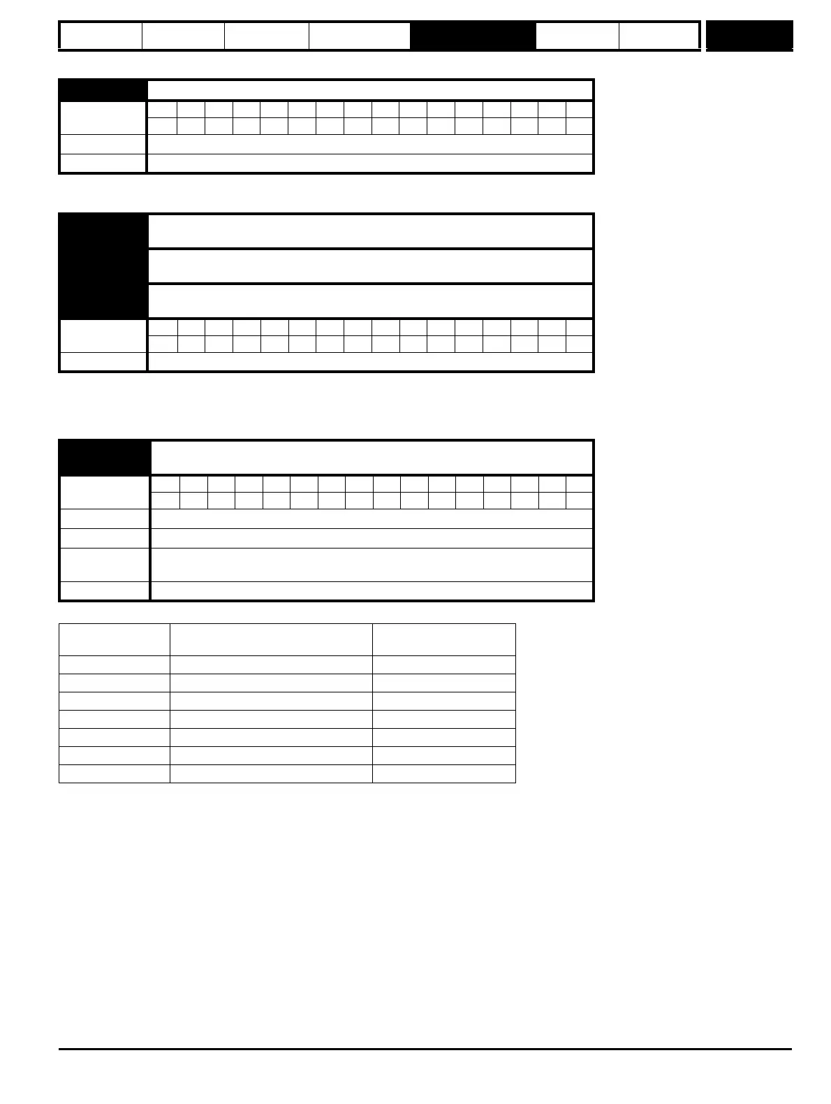
1.10 Bipolar reference enable
Coding
Bit SP FI DE Txt VM DP ND RA NC NV PT US RW BU PS
111
Default 0
Update rate 4 ms read
1.11
{di11, 0.46}
Reference enabled indicator
1.12
{di12, 0.47}
Reverse selected indicator
1.13
{di13, 0.48}
Jog selected indicator
Coding
Bit SP FI DE Txt VM DP ND RA NC NV PT US RW BU PS
1111
Update rate 4 ms read
1.14
{SE05, 0.26}
Reference selector
Coding
Bit SP FI DE Txt VM DP ND RA NC NV PT US RW BU PS
1 111
Range 0 to 6
Default 0 (A1.A2)
Second motor
parameter
Pr 21.03
Update rate 4 ms read
Value of Pr 1.14
{SE05, 0.26}
Display String Pr 1.49
0 A1.A2 (Analog ref 1. Analog ref 2) *Selected by terminal input
1 A1.Pr (Analog ref 1. Preset speeds) 1
2 A2.Pr (Analog ref 2. Preset speeds) 2
3 Pr (Preset speeds) 3
4 Pad (Keypad reference) 4
5 Prc (Precision reference) 5
6 Pad rEF 6