Menu 4
Parameter
structure
Keypad and
display
Parameter x.00
Parameter description
format
Advanced parameter
descriptions
Serial comms
protocol
Performance
62 Mentor MP Advanced User Guide
www.controltechniques.com Issue Number: 4
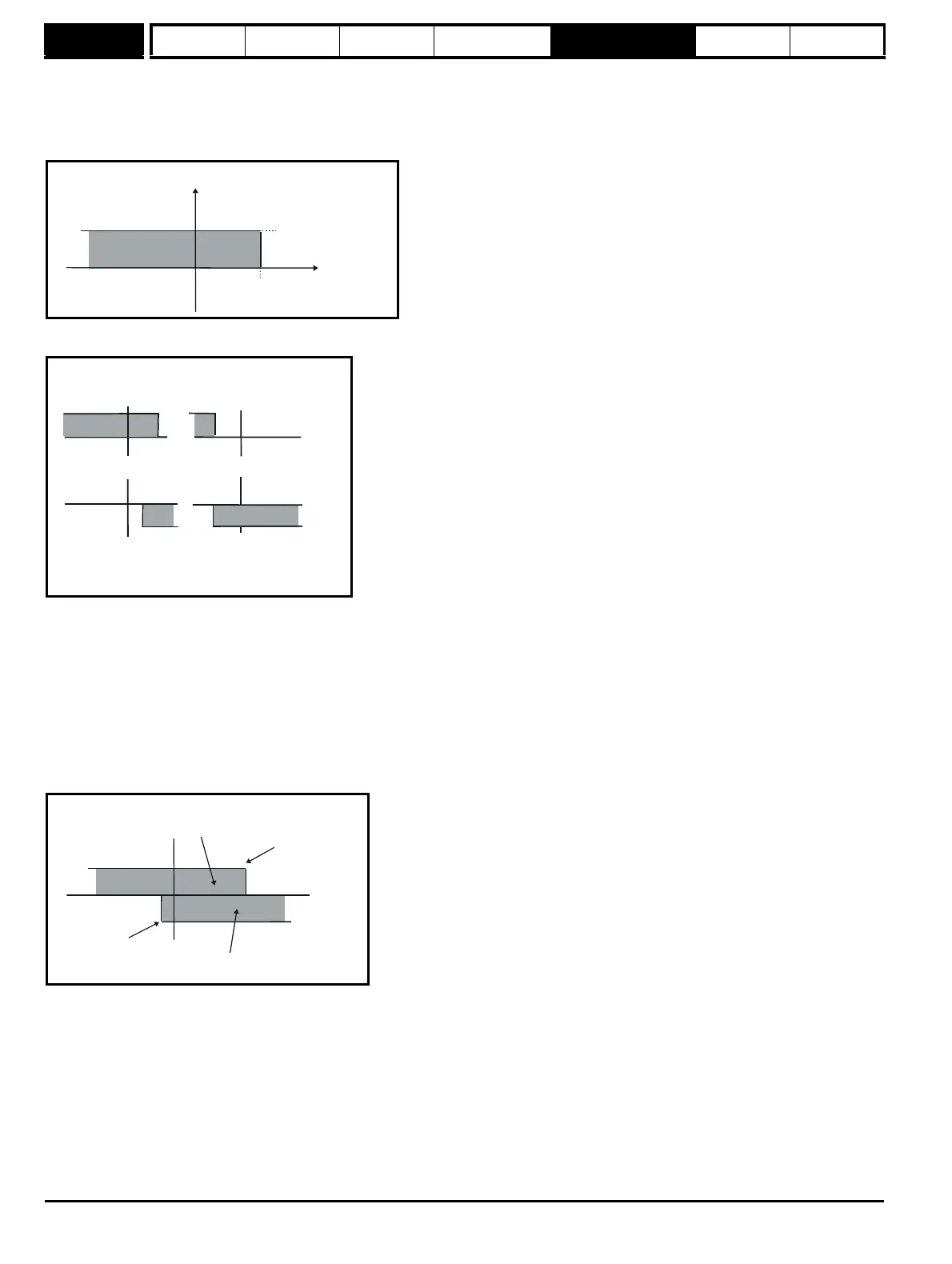
2: Torque control with speed override
The output of the speed loop defines the torque demand, but is limited between 0 and the resultant torque reference (Pr 4.08 + Pr 4.09 (if
enabled)). The effect is to produce an operating area as shown below if the final speed demand and the resultant torque reference are both
positive. The speed controller will try and accelerate the machine to the final speed demand level with a torque demand defined by the resultant
torque reference. However, the speed cannot exceed the reference because the required torque would be negative, and so it would be clamped
to zero.
Depending on the sign of the final speed demand and the resultant torque the four areas of operation shown below are possible.
This mode of operation can be used where torque control is required, but the maximum speed must be limited by the drive.
3: Coiler/uncoiler mode
Positive final speed demand: a positive resultant torque will give torque control with a positive speed limit defined by the final speed demand. A
negative resultant torque will give torque control with a negative speed limit of -5 rpm.
Negative final speed demand: a negative resultant torque will give torque control with a negative speed limit defined by the final speed demand. A
positive resultant torque will give torque control with a positive speed limit of +5 rpm.
Example of coiler operation:
This is an example of a coiler operating in the positive direction. The final speed demand is set to a positive value just above the coiler reference
speed. If the resultant torque demand is positive the coiler operates with a limited speed, so that if the material breaks the speed does not exceed a
level just above the reference. It is also possible to decelerate the coiler with a negative resultant torque demand. The coiler will decelerate down to -
5 rpm until a stop is applied. The operating area is shown in the following diagram:
Pr +
4.08
Pr (if enabled)
4.09
Pr
3.01
Speed
Current
+ final speed demand
+ resultant torque
- final speed demand
+ resultant torque
+ final speed demand
-resultant torque
- final speed demand
- resultant torque
Final speed
demand
Area for coiler operation, speed
limited to ref and positve torque
Area for decelerating the coiler, reverse
speed limited and negative torque
-5rpm
Speed
Torque