EasyManua.ls Logo

Curtis 1239E - User Manual

Curtis 1239E
160 pages
To Next Page IconTo Next Page
Loading...
Model 1239E & 1269E
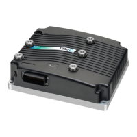
Enhanced Dual Voltage AC Controller
for PMAC and Induction Motors
Read Instructions Carefully!
Specications are subject to change without notice.
© 2021 Curtis Instruments, Inc. ® Curtis is a registered trademark of Curtis Instruments, Inc.
© The design and appearance of the products depicted herein are the copyright of Curtis Instruments, Inc. 53095, Rev A, May 2021
Curtis Instruments, Inc.
200 Kisco Avenue
Mt. Kisco, NY 10549
www.curtisinstruments.com
» Software Version OS 37.0 «
Manual

Table of Contents

Questions and Answers:

Curtis 1239E Specifications

General IconGeneral
BrandCurtis
Model1239E
CategoryController
LanguageEnglish

Summary

1 - INTRODUCTION

Getting the most out of the Curtis controller

How to apply and configure the controller for successful applications.

2 - INSTALLATION AND WIRING

MOUNTING THE CONTROLLER

Details on mounting dimensions, hole patterns, and mounting surface requirements for proper installation.

HIGH POWER CONNECTIONS

Information on the five high power terminals (B+, B-, U, V, W) and their connections.

LOW POWER 35-PIN CONNECTIONS

Details on the 35-pin AMPSEAL connector for low power circuits and pin assignments.

CONTROLLER WIRING: BASIC CONFIGURATION

Basic wiring diagram and configuration for main contactor and precharge.

SWITCH INPUT WIRING

Dedicates specific inputs to functions like interlock, forward, and reverse switches.

EXTERNAL PRECHARGE RESISTOR

Specifies requirements for the external precharge resistor when precharge is enabled.

LOW POWER CIRCUIT SPECIFICATIONS

Groups input/output circuits by type and discusses electrical characteristics.

DIGITAL INPUTS

Explains the use of control lines as digital inputs and their protection.

DIGITAL and PWM OUTPUT SPECIFICATIONS

Details specifications for digital and PWM output drivers, including current and frequency.

Analog Inputs

Describes the two control lines usable as analog inputs for sensors like thermistors.

Analog Output

Details the single low power analog output line for driving loads.

Power Supply Outputs

Describes auxiliary output power for low power circuits like throttles and displays.

KSI and Coil Return

Explains the KSI input for low power control and Coil Return for contactor driving.

COMMUNICATIONS PORT SPECIFICATIONS

Details CAN and serial port specifications for programming and communication.

Position Feedback Input: Quadrature Encoder

Explains the use of two control lines for quadrature position encoders in ACIM applications.

Position Feedback Input: Sin;Cos Sensor (encoder)

Details the use of Sin/Cos sensors for absolute position in PMAC applications.

Sin;Cos Sensor Device Electrical Specifications

Provides electrical specifications for Sin/Cos sensors, including voltage, frequency, and lag.

3 - APPLICATION-SPECIFIC FEATURES

THROTTLE

Discusses throttle usage, types, and fault protection for acceleration or braking control.

Throttle Type 1

Describes 2-wire 5kΩ–0 potentiometers and their wiring and parameter settings.

Throttle Type 3

Describes 2-wire 0–5kΩ potentiometers and their wiring and parameter settings.

Throttle Type 4

Describes wigwag 0–5V throttles and their operation.

Throttle Type 5

Explains using VCL for throttle signal input, offering flexibility and customization.

MOTOR SPEED CONSTRAINTS

Details the three constraints that define the maximum motor speed allowed by the controller.

VOLTAGE LIMITS

Explains overvoltage and undervoltage protection thresholds for high and low power circuits.

BATTERY DISCHARGE INDICATOR

Describes the BDI algorithm for calculating battery state-of-charge.

ISOLATION MONITOR

Explains the internal circuit that measures insulation resistance between high power and chassis.

4 - PROGRAMMABLE PARAMETERS

PROGRAMMING MENUS

Parameters are grouped into nested hierarchical menus for customization.

0 - SPEED MODE EXPRESS - SPEED MODE EXPRESS MENU

Parameters for simplified speed control, including Max Speed, Kp, Ki, and rates.

1 - SPEED MODE - SPEED CONTROLLER MENU

Parameters for speed control, including Max Speed, Kp, Ki LS/HS, and feedforward terms.

1 - SPEED MODE - RESPONSE MENU

Parameters to adjust vehicle response rates for acceleration, deceleration, and braking.

1 - SPEED MODE - FINE TUNING MENU

Parameters for fine-tuning speed mode, including reversal soften and speed acceleration/deceleration.

2 - TORQUE MODE MENU

Parameters for torque control mode, including speed limiter and response settings.

THROTTLE MENU

Parameters for configuring throttle input types, deadbands, mapping, and filtering.

BRAKE MENU

Parameters for configuring brake input types, deadbands, mapping, and filtering.

EM BRAKE CONTROL MENU

Parameters for controlling the electromagnetic brake function, including type, voltage, and timing.

DRIVERS MENU

Parameters for configuring individual driver outputs, including main contactor and driver 3.

MOTOR MENU

Parameters related to motor characteristics, including max speed and technology type.

0 - INDUCTION MOTOR (ACIM): CHARACTERIZATION TESTS

Parameters for ACIM motor auto-characterization to optimize performance.

MOTOR: FIELD WEAKENING CONTROL MENU

Parameters for adjusting field weakening to optimize efficiency or torque at high speeds.

MOTOR: LOS (LIMITED OPERATING STRATEGY) MENU

Parameters for Limited Operating Strategy (LOS) used in case of encoder faults.

MOTOR: 1 - PMAC (PERMANENT MAGENT MOTOR): COMMISSIONING TESTS MENU

Parameters for PMAC motor commissioning to learn motor data.

MOTOR: FEEDBACK OPTIONS MENU

Parameters for selecting and configuring feedback devices like encoders and Sin/Cos sensors.

MOTOR: FEEDBACK OPTIONS - FEEDBACK FAULT SETUP

Parameters for enabling and configuring encoder and sensor fault detection.

MOTOR: TEMPERATURE CONTROL MENU

Parameters for motor temperature monitoring, cutback, and compensation.

BATTERY MENU

Parameters for battery voltage settings, BDI, and insulation resistance monitoring.

BATTERY: BATTERY CURRENT LIMITING

Parameters to limit drive and regen battery current for battery protection.

VEHICLE MENU

Parameters for vehicle settings like units, speed-to-RPM conversion, and capture data.

INTERLOCK BRAKING MENU

Parameters for enabling and configuring interlock braking behavior.

CAN INTERFACE MENU

Parameters for configuring CANopen communication, node IDs, and message rates.

RESET CONTROLLER PARAMETER

Parameter to reset the controller to its default state, similar to cycling the keyswitch.

CLONING CONTROLLERS

Process for copying parameter settings between compatible controllers.

5 - MONITOR MENU

INPUTS MENU

Displays real-time values for all controller inputs, including throttle and switches.

OUTPUTS MENU

Displays real-time values for all controller outputs, including PWM and digital outputs.

VEHICLE MENU

Displays real-time vehicle data such as speed, odometer, and distance traveled.

CAN STATUS MENU

Displays CAN bus status, including Node IDs and NMT states.

BATTERY MENU

Displays battery status information like BDI, capacitor voltage, and insulation resistance.

MOTOR MENU

Displays motor status information such as RPM, temperature, and encoder feedback.

CONTROLLER MENU

Displays controller status, including current, state, errors, and VCL status.

MOTOR TUNING

Displays motor tuning parameters like Base Speed Captured and Test Field Current.

FOLLOWING ERROR - SPEED MODE

Displays following error and timer values related to speed control accuracy.

6 - CONTROLLER INFORMATION MENU

7 - INITIAL SETUP

Step 1: Motor Temperature Sensor

Guides setting up the motor temperature sensor type and verifying readings.

Step 2: Current Limits

Details setting drive, regen, brake, EMR, and interlock current limits.

Step 3: Battery

Instructions for setting the nominal battery pack voltage and considering Li-ion battery recommendations.

Step 4: Main Contactor

Instructions to set up parameters in the Drivers » Main Contactor Menu.

Step 5: EM Brake

Instructions to set up parameters in the EM Brake Control Menu if applicable.

Step 6: Throttle

Guides verifying interlock and setting up throttle type, deadbands, and mapping.

Step 7: Brake

Guides verifying interlock and configuring brake parameters like type, deadbands, and mapping.
Step 8: Motor Technology & Feedback Type

Sets Motor Technology and Feedback Type to match the motor and sensor.

Step 9: Faults (see Chapter 11)

Checks and clears all controller faults and errors before proceeding with setup.

Step 10: Setting Feedback Direction

Checks and sets the correct motor rotation direction based on encoder feedback.

Step 11: Motor Characterization

Procedures for ACIM motor characterization to learn motor data and optimize performance.

Step 12: Checking Direction of Rotation

Verifies motor rotation direction after encoder setup and checks for correct response.

Step 13: Interlock Braking

Instructions to set up parameters in the Interlock Braking Menu.

Step 14: High Voltage Battery Insulation Resistance & Threshold Setting (optional)

Optional step for setting up the insulation resistance monitor and threshold.

Steps 15: as Applicable

Applicable steps for setting Response Restraint and Position Hold parameters.

8 A - AUTOMATED ACIM MOTOR CHARACTERIZATION PROCEDURE

TRACTION SYSTEMS

Steps intended for traction applications, including verifying settings and motor parameters.

8 B - AUTOMATED PMAC MOTOR COMMISSIONING PROCEDURE

9 - TUNING GUIDE

Selecting the Control Mode

Guides selecting the control mode (Speed Express, Speed, or Torque) for tuning.

0 − Speed Mode Express Tuning

Tuning procedures for Speed Mode Express, adjusting Max Speed, Kp, Ki, and rates.

1 − Speed Mode Tuning

Tuning procedures for Speed Mode, adjusting Kp, Ki, rates, and restraint parameters.

2 − Torque Mode Tuning

Tuning procedures for Torque Mode, adjusting Max Speed, Kp, Ki, Kd, and throttle mapping.

10 - VEHICLE CONTROL LANGUAGE (VCL)

Summary of VCL Basics

Provides basic syntax rules, variable types, and function structure for VCL.

VARIABLE TYPES

Explains VCL variable storage types: RAM, NVUser EEPROM, Block EEPROM, and Parameters EEPROM.

VCL RUNTIME RATES

Details processing rates for various VCL functions.

I;O CONTROL WITH VCL

Explains how to control digital inputs, driver/digital outputs using VCL functions.

Potentiometer Inputs

Describes using potentiometer inputs for throttle, brake, or other sensor inputs via VCL.

Throttle Processing

Details how the throttle signal chain is processed and modified by VCL.

Brake Processing

Details how the brake signal chain is processed and modified by VCL.

Control Mode and Motor Control Processing

Explains how control mode and motor control processing use throttle/brake signals.

INTERFACING THE PROPORTIONAL CURRENT DRIVER

Information on interfacing with proportional current drivers, typically not used with this controller.

USING THE FAULT HANDLER IN VCL

Explains how to use system fault status variables in VCL for custom fault actions.

CANbus Emergency Messages

Describes how Status faults map to CAN emergency messages.

OEM-defined User Faults

Explains creating and using OEM-defined custom faults with VCL.

VCL FUNCTIONS SPECIFIC TO 1239 E;1269 E CONTROLLERS

Details specific VCL functions unique to these controllers, like precharge.

ENABLE_PRECHARGE()

Function to precharge the capacitor bank before engaging the main contactor.

DISABLE_PRECHARGE()

Function to abort the precharge function and clear any precharge fault.

SET_DIGOUT()

VCL function to turn digital outputs On or Off.

CLEAR_DIGOUT()

VCL function to turn digital outputs Off.

SET_INTERLOCK()

VCL function to engage the system interlock.

CLEAR_INTERLOCK()

VCL function to disengage the system interlock.

SETUP_POT()

Function to determine potentiometer input connection type.

GET_POT()

Function to return the value of a selected potentiometer input.

SETUP_POT_FAULTS()

Function to re-set upper and lower wiper fault voltages for pot inputs.

AUTOMATE_FREQUENCY_OUTPUT()

Function to set up PD Driver PWM for frequency proportional output.

MAP_TWO_POINTS()

Function to interpolate values between two points based on an input parameter.

BATTERY_COMPENSATE()

Function to compensate a variable with battery voltage using nominal setting.

PUT_MESSAGE_TO_STRING()

Function to construct an ASCII message with pre-text, variable value, and post-text.

AUTOMATE_PWM_INPUT()

Configures a switch input to measure PWM signal duty cycle.

SETUP_TIMER_LONG()

Allows a 32-bit variable to set a timer value.

SETUP_MAILBOX_MASK()

Sets up a mask to allow messages with multiple COB IDs.

SETUP_MAILBOX_EXTENDED_MASK()

Sets up a mask for multiple 29-bit COB IDs.

AUTOMATE_ENCODER()

Allows processing of low bandwidth Sin/Cos signals for VCL use.

11 - DIAGNOSTICS AND TROUBLESHOOTING

DIAGNOSTICS

Explains obtaining diagnostic information via programmer or LED codes.

Identifying Prototype Software

Discusses software verification status indication via LED blink patterns.

TROUBLESHOOTING

Provides a chart detailing fault codes, effects, causes, and set/clear conditions.

APPENDIX A

ELECTROMAGNETIC COMPATIBILITY (EMC)

Discusses emissions, immunity, and techniques to reduce EMC risks.

ELECTROSTATIC DISCHARGE (ESD) IMMUNITY

Details the need to protect ESD-sensitive components from ESD damage.

DECOMMISSIONING AND RECYCLING THE CONTROLLER

Provides guidance on controller decommissioning and recycling procedures.

APPENDIX B

EN13849 COMPLIANCE

Explains compliance with safety standards like EN13849, including Performance Level (PL).

APPENDIX C

PROGRAMMING DEVICES

Introduces Curtis programming devices (1314 PC Station, 1313 Handheld) and their functions.

PC PROGRAMMING STATION (1314)

Details the PC Programming Station software and hardware requirements.

HANDHELD PROGRAMMER (1313)

Describes the handheld programmer's functionality and advantages.

PROGRAMMER FUNCTIONS

Outlines the capabilities of programmers: parameter adjustment, monitoring, diagnostics, and programming.

APPENDIX D

CONTROLLER SPECIFICATIONS

Lists detailed specifications for 1239E and 1269E controllers, including electrical and environmental ratings.

Related product manuals