CVC TECHNOLOGIES, INC. CVC 400 OPERATION MANUAL
7 - 9
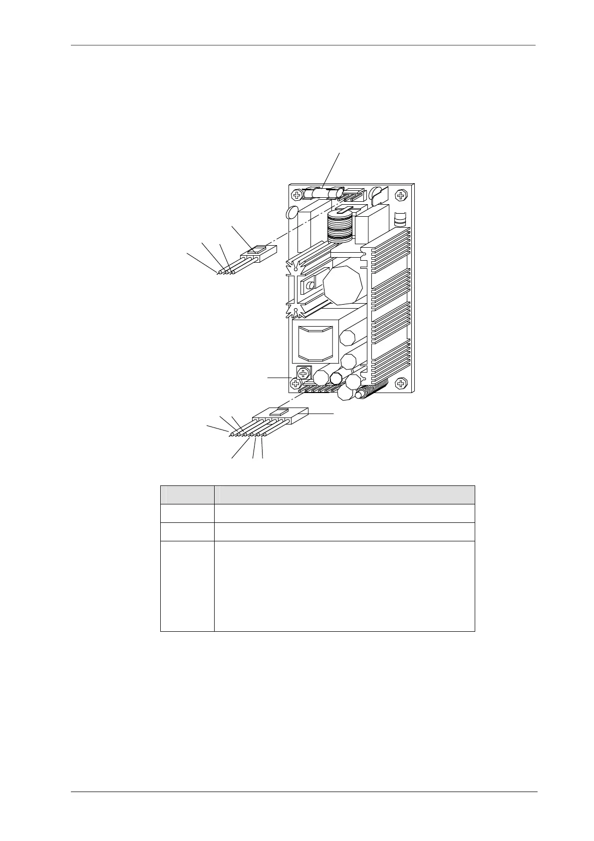
7.2.5 C17: DC Power Supply
If LED D41on interface board is not lit when power is on, it indicates no output for switch power 5V. If
LED D42 is not lit when power is on, it indicates no output for switch power 12V, replace a new one if
necessary.
Item Function
CN1 AC power input: AC 85~265V
FS1 Fuse: 4A (20mm)
CN2 DC 5V/12V
Black wire (BK): 12V
Brown wire (BR): 12VG
Red (R) and Orange (O): 5V
Yellow (Y) and Green (G): 5VG
FS1
AC
FG
AC
CN1
DC OUT
BR
Y
G
R O
BK
CN2