1 Product Introduction D-Link DXS-1210 Series User Manual
4
Reset: By pressing the Reset button, the Switch will change back to the default configuration and all
changes will be lost.
Rear Panel
Figure 1.4 – DXS-1210-12TC Rear Panel
Power: Connect the AC power cord to this port.
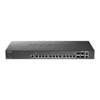
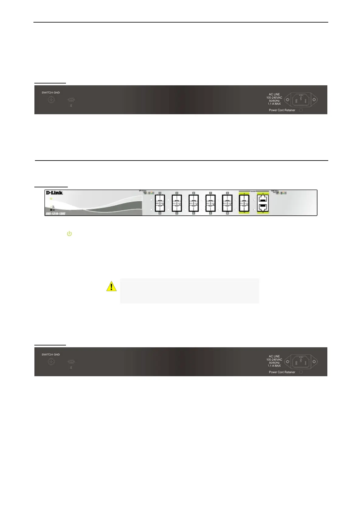
DXS-1210-12SC
10-Port 10G SFP+ fiber port and 2-port 10GBASE-T/SFP + combo port L2 10 Gigabit Ethernet Switch.
Front Panel
Figure 1.5 – DXS-1210-12SC Front Panel
Power LED : The Power LED lights up when the Switch is connected to a power source.
Fan error: The Fan error LED lights up when the fan has runtime failure and is brought offline.
Port Link/Act/Speed LED (1-10, 11F, 12F): The Link/Act/Speed LED flashes, which indicates a network link
through the corresponding port. Blinking indicates that the Switch is either sending or receiving data to the
port. When a port has an amber light, this indicates that the port is running on 100M or 1000M. When it has a
green light it is running on 10Gbps.
CAUTION: The MiniGBIC ports should use UL
listed Optical Transceiver product, Rated Laser
Class I. 3.3Vdc.
Reset: By pressing the Reset button, the Switch will change back to the default configuration and all
changes will be lost.
Rear Panel
Figure 1.6 – DXS-1210-12SC Rear Panel
Power: Connect the AC power cord to this port.
 Loading...