EasyManuals Logo

Danfoss VLT AutomationDrive Design Guide

Danfoss VLT AutomationDrive
281 pages
To Next Page IconTo Next Page
To Previous Page IconTo Previous Page
Page #163 background imageLoading...
Page #163 background image
U
V
W
96
97
98
130BT337.10
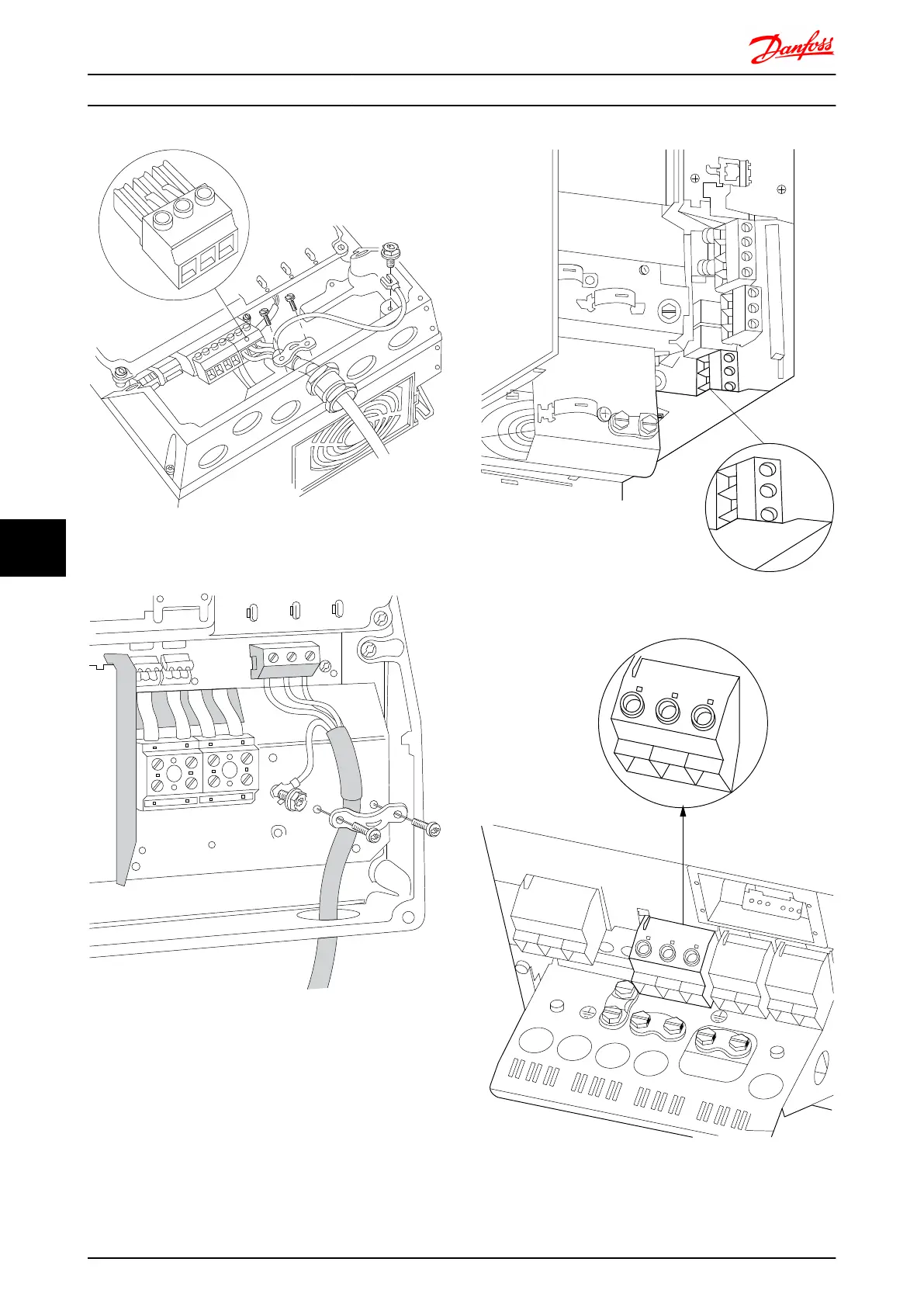
Illustration 8.8 Motor connection for size A4/A5 (IP55/66/NEMA
Type 12)
130BT333.10
Illustration 8.9 Motor connection for size B1 and B2 (IP21/ NEMA
Type 1, IP55/ NEMA Type 12 and IP66/ NEMA Type 4X)
130BA726.10
Illustration 8.10 Motor connection for size B3.
U
96
V
97
W
98
U
96
V
97
W
98
L1
91
L2
92
L3
93
DC-
88
DC+
89
R-
81
R+
82
130BA721.10
99
Illustration 8.11 Motor connection for frame size B4 .
Electrical Installation FC 300 Design Guide
162 MG.33.BD.02 - VLT
®
is a registered Danfoss trademark
88

Table of Contents

Other manuals for Danfoss VLT AutomationDrive

Questions and Answers:

Question and Answer IconNeed help?

Do you have a question about the Danfoss VLT AutomationDrive and is the answer not in the manual?

Danfoss VLT AutomationDrive Specifications

General IconGeneral
Supply Voltage3 x 200-240 V ±10% 3 x 380-500 V ±10% 3 x 525-600 V ±10%
EnclosureIP20
Output Power Range0.25 kW - 1.5 MW
Communication ProtocolsModbus RTU
Protection FeaturesOvercurrent, Overvoltage, Undervoltage, Short circuit, Ground fault, Motor overload
Ambient Temperature Range-10°C to +50°C (14°F to 122°F)

Related product manuals