91
L1
92
L2
93
L3
96
U
97
V
98
W
88
DC-
89
DC+
81
R-
8
R+
130BA390.11
99
95
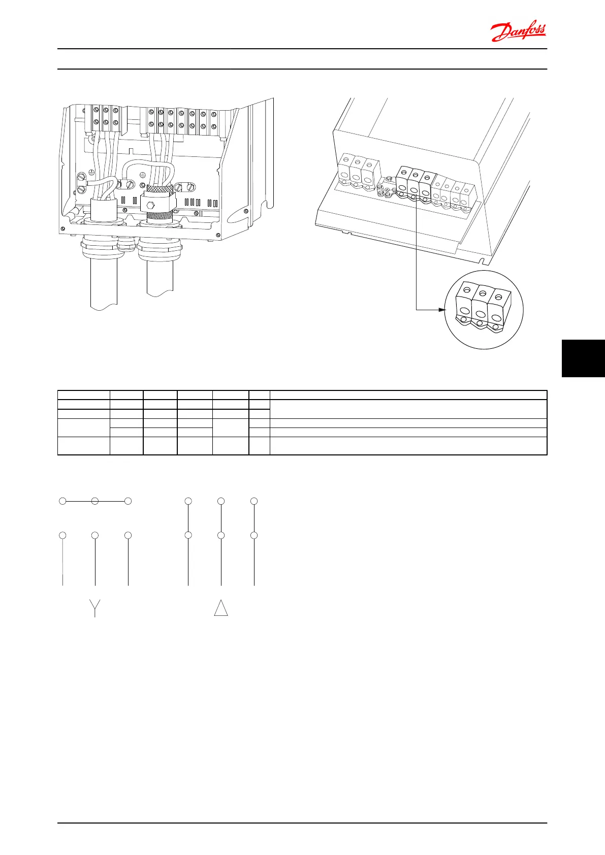
Illustration 8.12 Motor connection frame size C1 and C2 (IP21/
NEMA Type 1 and IP55/66/ NEMA Type 12)
130BA740.10
DC-
DC+
R-
R+
88
89
81
82
97
U
V
W
99
96
98
L1
91
L2
92
L3
93
97
U
V
W
96
98
Illustration 8.13 Motor connection for frame size C3 and C4.
Term. no. 96 97 98 99
U V W
PE
1)
Motor voltage 0-100% of mains voltage.
3 wires out of motor
U1 V1 W1
PE
1)
Delta-connected
W2 U2 V2 6 wires out of motor
U1 V1 W1
PE
1)
Star-connected U2, V2, W2
U2, V2 and W2 to be interconnected separately.
1)
Protected Earth Connection
U V W
175ZA114.10
VU W
96 97 98
96 97 98
In motors without phase insulation paper or other
insulation reinforcement suitable for operation with
voltage supply (such as a frequency converter), fit a Sine-
wave filter on the output of the frequency converter.
Electrical Installation FC 300 Design Guide
MG.33.BD.02 - VLT
®
is a registered Danfoss trademark 163
8 8

 Loading...


