[6]
[5]
[3]
[2]
[4]
[1]
130BB669.10
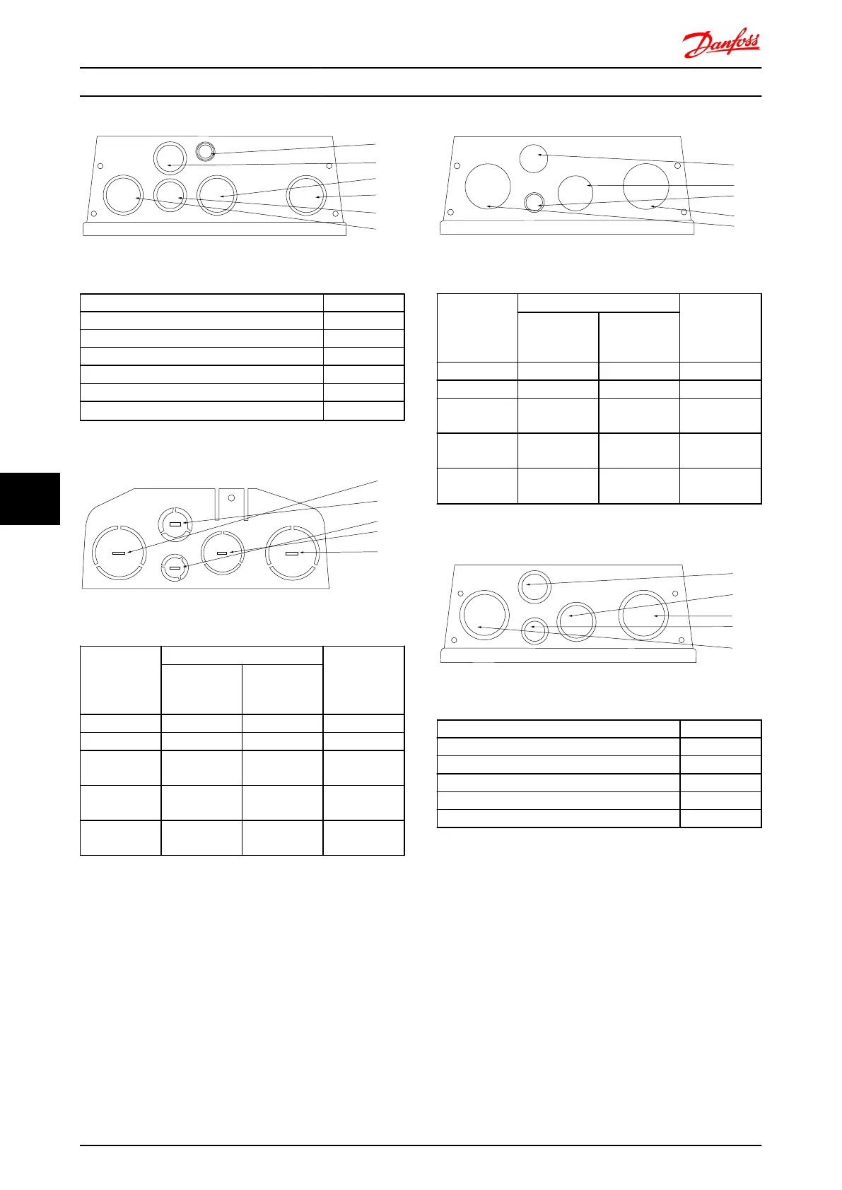
Illustration 8.22 B1 - IP55 threaded gland holes
Hole Number and recommended use Dimensions
1) Mains M32
2) Motor M32
3) Brake/Load Sharing M32
4) Control Cable M25
5) Control Cable M25
6) Control Cable
22.5 mm
1)
1)
Knock-out hole
[1]
[4]
[5]
[3]
[2]
130BB660.10
Illustration 8.23 B2 - IP21
Hole Number
and
recommended
use
Dimensions
1)
Nearest metric
UL [in] [mm]
1) Mains 1 1/4 44.2 M40
2) Motor 1 1/4 44.2 M40
3) Brake/Load
Sharing
1 34.7 M32
4) Control
Cable
3/4 28.4 M25
5) Control
Cable
1/2 22.5 M20
1)
Tolerance
±
0.2 mm
[4]
[3]
[5]
[2]
[1]
130BB668.10
Illustration 8.24 B2 - IP55
Hole Number
and
recommended
use
Dimensions
1)
Nearest metric
UL [in] [mm]
1) Mains 1 1/4 44.2 M40
2) Motor 1 1/4 44.2 M40
3) Brake/Load
Sharing
1 34.7 M32
4) Control
Cable
3/4 28.4 M25
5) Control
Cable
2)
1/2 22.5 M20
1)
Tolerance
±
0.2 mm
2)
Knock-out hole
[4]
[3]
[2]
[5]
[1]
130BB670.10
Illustration 8.25 B2 - IP55 threaded gland holes
Hole Number and recommended use Dimensions
1) Mains M40
2) Motor M40
3) Brake/Load Sharing M32
4) Control Cable M25
5) Control Cable M20
Electrical Installation FC 300 Design Guide
166 MG.33.BD.02 - VLT
®
is a registered Danfoss trademark
88

 Loading...


