EasyManuals Logo

Danfoss VLT AutomationDrive Design Guide

Danfoss VLT AutomationDrive
281 pages
To Next Page IconTo Next Page
To Previous Page IconTo Previous Page
Page #178 background imageLoading...
Page #178 background image
3
5
6
4, 8, 9
21
7
130BA861.10
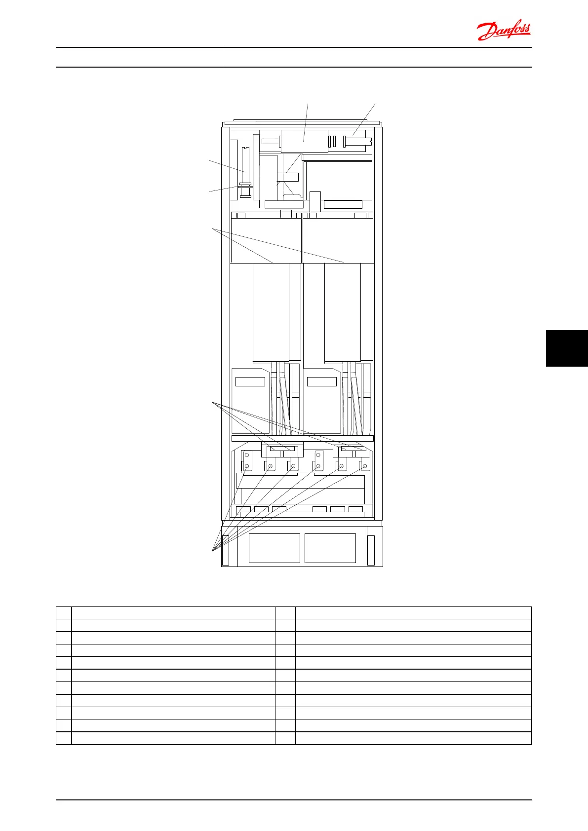
Illustration 8.40 Inverter Cabinet, frame size F1 and F3
1)
External Temperature Monitoring 6) Motor
2) AUX Relay U V W
01 02 03 96 97 98
04 05 06 T1 T2 T3
3) NAMUR 7) NAMUR Fuse. See fuse tables for part numbers
4) AUX Fan 8) Fan Fuses. See fuse tables for part numbers
100 101 102 103 9) SMPS Fuses. See fuse tables for part numbers
L1 L2 L1 L2
5) Brake
-R +R
81 82
Electrical Installation FC 300 Design Guide
MG.33.BD.02 - VLT
®
is a registered Danfoss trademark 177
8 8

Table of Contents

Other manuals for Danfoss VLT AutomationDrive

Questions and Answers:

Question and Answer IconNeed help?

Do you have a question about the Danfoss VLT AutomationDrive and is the answer not in the manual?

Danfoss VLT AutomationDrive Specifications

General IconGeneral
Supply Voltage3 x 200-240 V ±10% 3 x 380-500 V ±10% 3 x 525-600 V ±10%
EnclosureIP20
Output Power Range0.25 kW - 1.5 MW
Communication ProtocolsModbus RTU
Protection FeaturesOvercurrent, Overvoltage, Undervoltage, Short circuit, Ground fault, Motor overload
Ambient Temperature Range-10°C to +50°C (14°F to 122°F)

Related product manuals