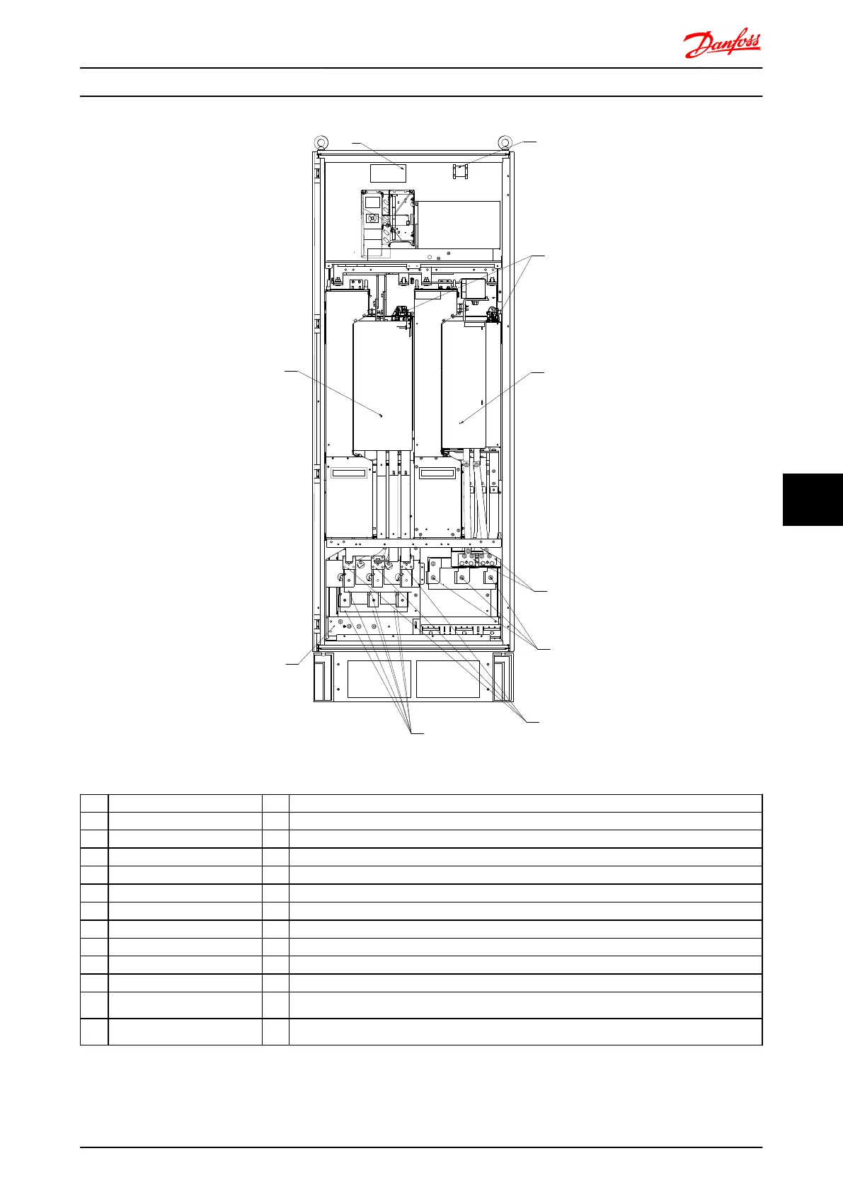
Illustration 8.44 Rectifier and Inverter Cabinet, frame size F8 and F9
1)
12-pulse rectifier module 5) Motor connection
2) Ground / Earth PE Terminals U V W
3) Line / Fuses T1 T2 T3
R1 S1 T1 96 97 98
L1-1 L2-1 L3-1 6) Brake Terminals
91-1 92-1 93-1 -R +R
4) Line / Fuses 81 82
R2 S2 T2 7) Inverter Module
L2-1 L2-2 L3-2 8) SCR Enable / Disable
91-2 92-2 93-2 9) Relay 1 Relay 2
01 02 03 04 05 06
10) Auxillary Fan
104 106
Electrical Installation FC 300 Design Guide
MG.33.BD.02 - VLT
®
is a registered Danfoss trademark 183
8 8

 Loading...


