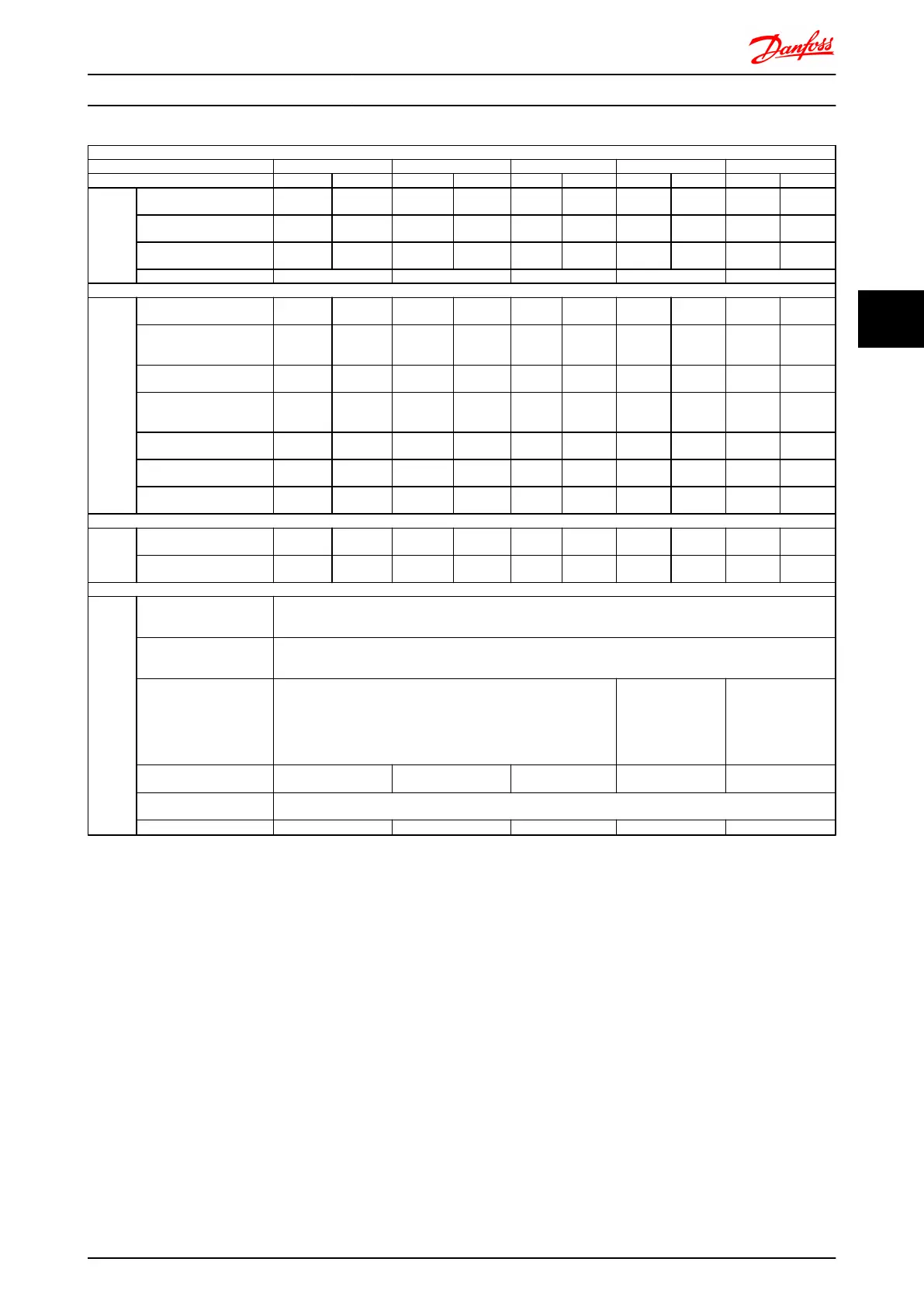
Mains Supply 3 x 525- 690V AC
FC 302 P30K P37K P45K P55K P75K
High/ Normal Load* HO NO HO NO HO NO HO NO HO NO
Typical Shaft output at
550V [kW]
22 30 30 37 37 45 45 55 55 75
Typical Shaft output at
575V [HP]
30 40 40 50 50 60 60 75 75 100
Typical Shaft output at
690V [kW]
30 37 37 45 45 55 55 75 75 90
Enclosure IP21, 55 C2 C2 C2 C2 C2
Output current
Continuous
(3 x 525-550V) [A]
36 43 43 54 54 65 65 87 87 105
Intermittent (60 sec
overload)
(3 x 525-550V) [A]
54 47.3 64.5 59.4 81 71.5 97.5 95.7 130.5 115.5
Continuous
(3 x 551-690V) [A]
34 41 41 52 52 62 62 83 83 100
Intermittent (60 sec
overload)
(3 x 551-690V) [A]
51 45.1 61.5 57.2 78 68.2 93 91.3 124.5 110
Continuous KVA
(at 550V) [KVA]
34.3 41.0 41.0 51.4 51.4 61.9 61.9 82.9 82.9 100.0
Continuous KVA
(at 575V) [KVA]
33.9 40.8 40.8 51.8 51.8 61.7 61.7 82.7 82.7 99.6
Continuous KVA
(at 690V) [KVA]
40.6 49.0 49.0 62.1 62.1 74.1 74.1 99.2 99.2 119.5
Max. input current
Continuous
(at 550V) [A]
36 49 49 59 59 71 71 87 87 99
Continuous
(at 575V) [A]
54 53.9 72 64.9 87 78.1 105 95.7 129 108.9
Additional specifications
Max. cable cross section
(mains and motor) [mm
2
(AWG)]
150 (300MCM)
Max. cable cross section
(load share and brake)
[mm
2
(AWG)]
95 (3/0)
Max cable size with mains
disconnect [mm
2
(AWG)]
2)
95, 70, 70
(3/0, 2/0, 2/0)
185, 150, 120
(350MCM, 300MCM,
4/0)
-
Estimated power loss
at rated max. load [W]
4)
480 592 720 880 1200
Weight,
enclosure IP21, IP55 [kg]
65
Efficiency
4)
0.98 0.98 0.98 0.98 0.98
For fuse ratings, see 8.3.1 Fuses
1) High overload = 160% torque during 60 sec., Normal overload = 110% torque during 60 sec.
2) American Wire Gauge.
3) Measured using 5 m screened motor cables at rated load and rated frequency.
4) The typical power loss is at nominal load conditions and expected to be within +/-15% (tolerence relates to variety in voltage and
cable conditions).
Values are based on a typical motor efficiency (eff2/eff3 border line). Motors with lower efficiency will also add to the power loss in the
frequency converter and opposite.
If the switching frequency is increased compared to the default setting, the power losses may rise significantly.
LCP and typical control card power consumptions are included. Further options and customer load may add up to 30W to the losses.
(Though typical only 4W extra for a fully loaded control card, or options for slot A or slot B, each).
Although measurements are made with state of the art equipment, some measurement inaccuracy must be allowed for (+/-5%).
5) The three values for the max. cable cross section are for single core, flexible wire and flexible wire with sleeve, respectively.
FC 300 Selection FC 300 Design Guide
MG.33.BD.02 - VLT
®
is a registered Danfoss trademark 75
4 4

 Loading...


