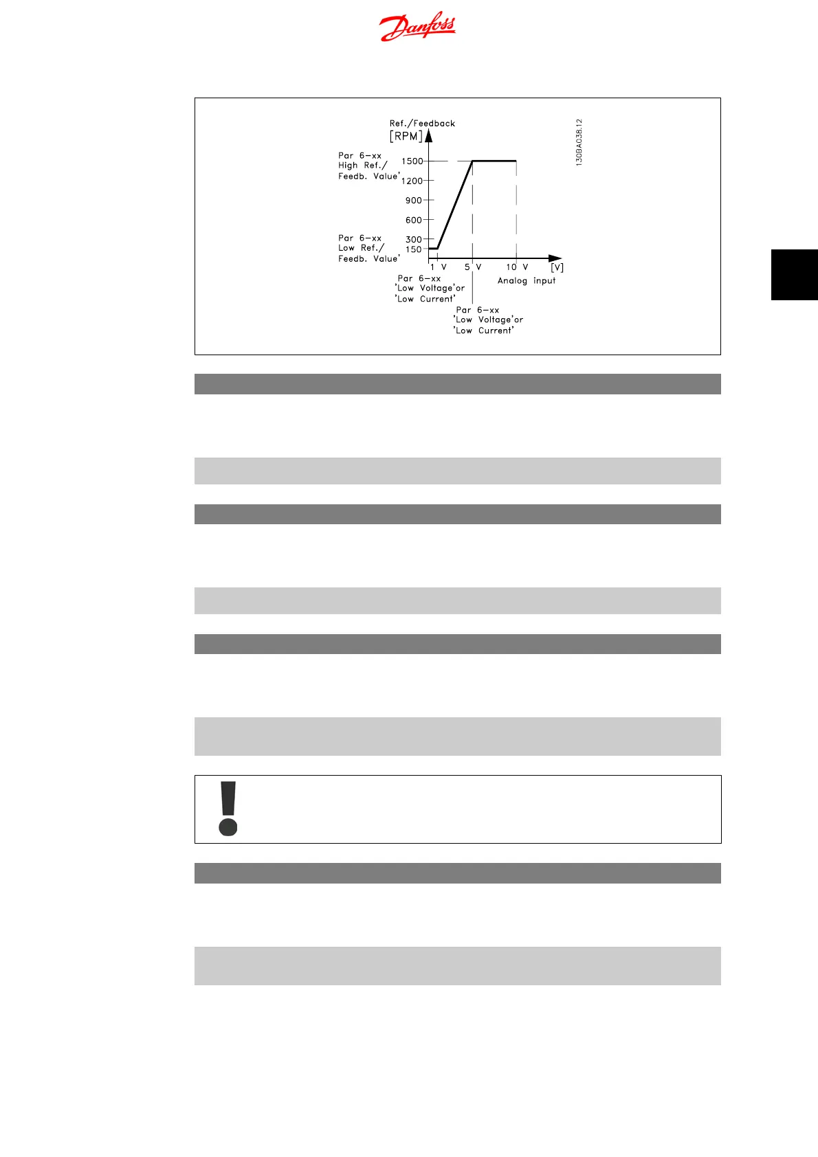
6-10 Terminal 53 Low Voltage
Range: Function:
This scaling value should correspond to minimum reference val-
ue set in par. 6-14. See also section
Reference Handling
.
0.07 V
*
[0.00 - 9.90 V] Enter low voltage value.
6-11 Terminal 53 High Voltage
Range: Function:
This scaling value should correspond to maximum reference
value set in par. 6-15.
10.0 V
*
[0.10 - 10.00 V] Enter high voltage value.
6-12 Terminal 53 Low Current
Range: Function:
This reference signal should correspond to minimum reference
value set in par. 3-02.
0.14
mA
*
[0.00 - 19.90 mA] Enter low current value.
The value must be set to min. 2 mA in order to activate the Live Zero Timeout
function in par. 6-01.
6-13 Terminal 53 High Current
Range: Function:
This reference signal should correspond to the maximum refer-
ence value set in par. 6-15.
20.00
mA
*
[0.10 - 20.00 mA] Enter high current value.
VLT Micro Drive FC 51 4. Parameter Descriptions
MG.02.C2.02 - VLT
®
is a registered Danfoss trademark
45
4
 Loading...


