7.10.3 Force/Write Multiple Coils (0F HEX)
Description
This function forces each coil in a sequence of coils to
either ON or OFF. When broadcasting the function forces
the same coil references in all attached followers.
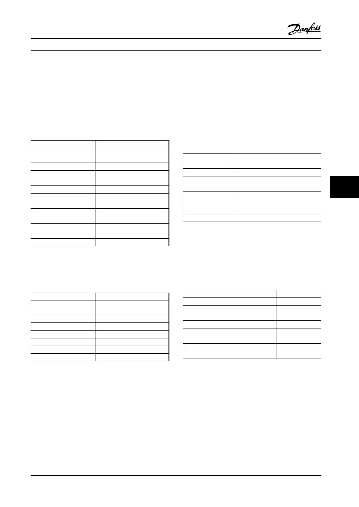
Query
The query message specifies the coils 17 to 32 (speed
setpoint) to be forced.
Field Name Example (HEX)
Follower Address 01 (adjustable frequency drive
address)
Function 0F (write multiple coils)
Coil Address HI 00
Coil Address LO 10 (coil address 17)
Quantity of Coils HI 00
Quantity of Coils LO 10 (16 coils)
Byte Count 02
Force Data HI
(Coils 8-1)
20
Force Data LO
(Coils 16-9)
00 (ref.=2000 hex)
Error Check (CRC) -
Table 7.25 Query
Response
The normal response returns the follower address, function
code, starting address, and quantity of coils forced.
Field Name Example (HEX)
Follower Address 01 (adjustable frequency drive
address)
Function 0F (write multiple coils)
Coil Address HI 00
Coil Address LO 10 (coil address 17)
Quantity of Coils HI 00
Quantity of Coils LO 10 (16 coils)
Error Check (CRC) -
Table 7.26 Response
7.10.4
Read Holding Registers (03 HEX)
Description
This function reads the contents of holding registers in the
follower.
Query
The query message specifies the starting register and
quantity of registers to be read. Register addresses start at
zero, that is, registers 1-4 are addressed as 0-3.
Example: Read 3-03 Maximum Reference, register 03030.
Field Name Example (HEX)
Follower Address 01
Function 03 (read holding registers)
Starting Address HI 0B (Register address 3029)
Starting Address LO 05 (Register address 3029)
No. of Points HI 00
No. of Points LO
02 - (3-03 Maximum Reference is 32 bits
long, i.e., two registers)
Error Check (CRC) -
Table 7.27 Query
Response
The register data in the response message are packed as
two bytes per register, with the binary contents right
justified within each byte. For each register, the first byte
contains the high-order bits and the second contains the
low-order bits.
Field Name Example (HEX)
Follower Address 01
Function 03
Byte Count 04
Data HI (Register 3030) 00
Data LO (Register 3030) 16
Data HI (Register 3031) E3
Data LO (Register 3031) 60
Error Check (CRC) -
Table 7.28 Response
RS-485 Installation and Set... Design Guide
MG18C522 Danfoss A/S © Rev. 2014-01-14 All rights reserved. 101
7 7

 Loading...


