5.2.2 Connecting to Line Power and Motor
The adjustable frequency drive is designed to operate all
standard 3-phased asynchronous motors. For maximum
cross-section on wires, see chapter 8.2 General Specifi-
cations.
•
Use a shielded/armored motor cable to comply
with EMC emission specifications, and connect
this cable to both the decoupling plate and the
motor metal.
•
Keep motor cable as short as possible to reduce
the noise level and leakage currents.
•
For further details on mounting of the
decoupling plate, see FC 101 Decoupling Plate
Mounting Instruction.
•
Also see EMC-compatible Installation in the VLT
®
HVAC Basic Design Guide.
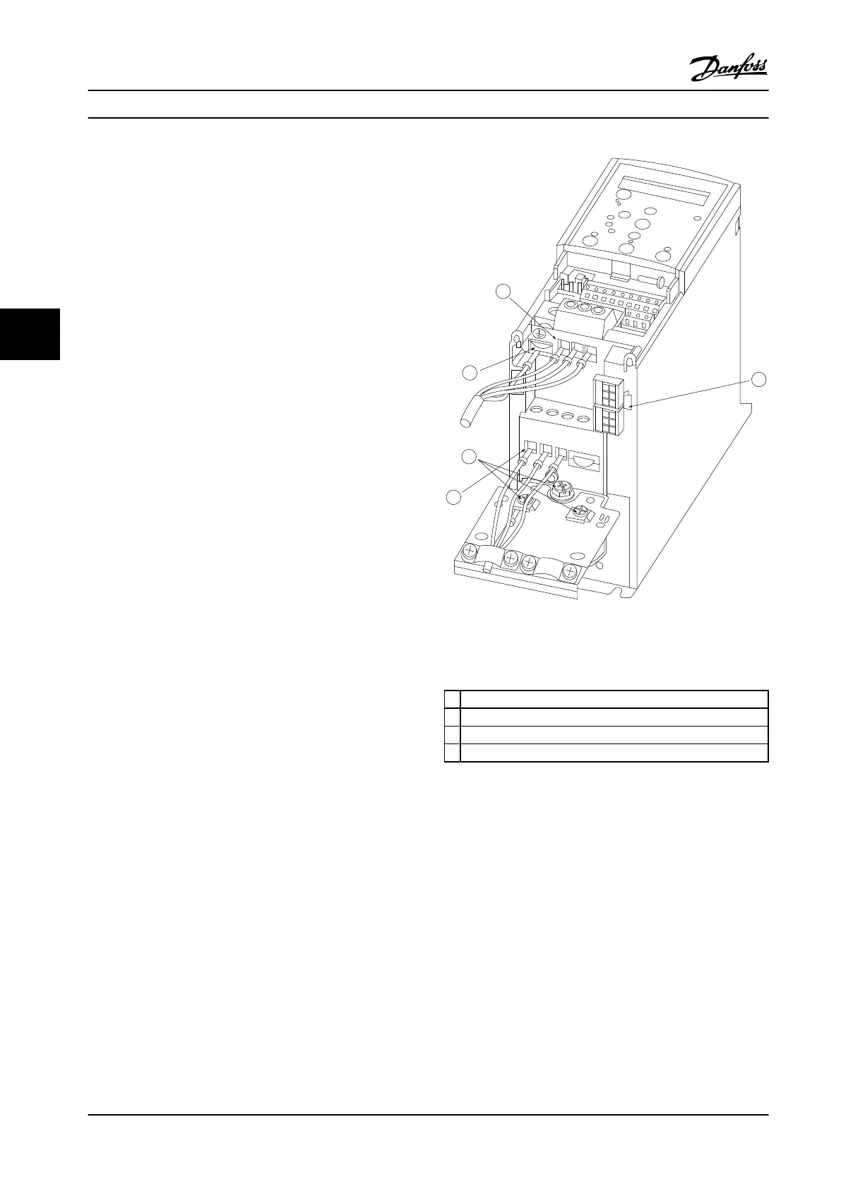
1. Mount the ground wires to the ground terminal.
2. Connect the motor to terminals U, V and W.
3. Mount line power supply to terminals L1, L2 and
L3 and tighten.
130BB634.10
1
2
2
3
4
Motor
U
V
W
-DC
+DC
MAINS
Figure 5.2 H1-H5 Frame
IP20 200–240 V 0.34–15 hp [0.25–11 kW] and IP20 380–480 V
0.5–30 hp [0.37–22 kW].
1
Line
2 Ground
3 Motor
4 Relays
Table 5.7 Legend to Figure 5.2
How to Install Design Guide
60 Danfoss A/S © Rev. 2014-01-14 All rights reserved. MG18C522
55

 Loading...


