2.8 General Aspects of EMC
Electrical interference is usually conducted at frequencies in the range 150 kHz to 30 MHz. Airborne interference from the
adjustable frequency drive system in the range 30 MHz to 1 GHz is generated from the inverter, motor cable, and the
motor.
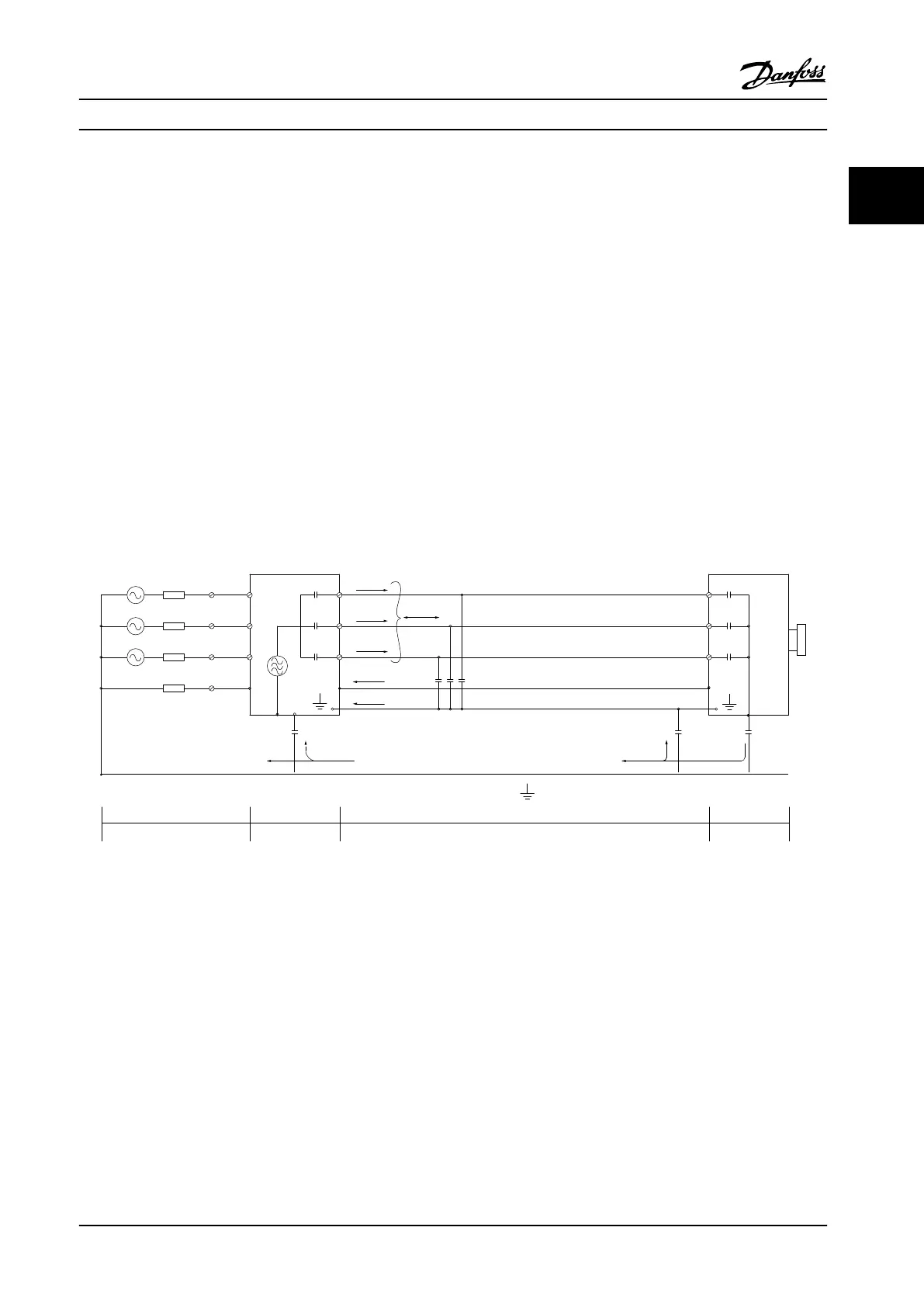
As shown in Figure 2.23, capacitive currents in the motor cable coupled with a high dU/dt from the motor voltage generate
leakage currents.
The use of a shielded motor cable increases the leakage current (see Figure 2.23) because shielded cables have higher
capacitance to ground than non-shielded cables. If the leakage current is not filtered, it causes greater interference on the
line power in the radio frequency range below approximately 5 MHz. Since the leakage current (I
1
) is carried back to the
unit through the shielding (I
3
), there will in principle only be a small electro-magnetic field (I
4
) from the shielded motor
cable according to the figure below.
The shield reduces the radiated interference, but increases the low-frequency interference in the line power supply. The
motor cable screen must be connected to the adjustable frequency drive enclosure as well as to the motor enclosure. This
is best done by using integrated shield clamps so as to avoid twisted shield ends (pigtails) These increase the shield
impedance at higher frequencies, which reduces the shield effect and increases the leakage current (I
4
).
If a shielded cable is used for serial communication bus, relay, control cable, signal interface and brake, the shield must be
mounted on the enclosure at both ends. In some situations, however, it is necessary to break the shield to avoid current
loops.
1
2
z
z
z
L1
L2
L3
PE
U
V
W
C
S
I
2
I
1
I
3
I
4
C
S
C
S
C
S
C
S
I
4
C
S
z
PE
3
4
5
6
Figure 2.23 Situation that Generates Leakage Currents
If the shield is to be placed on a mounting plate for the adjustable frequency drive, the mounting plate must be made of
metal, because the shield currents have to be conveyed back to the unit. Moreover, ensure good electrical contact from the
mounting plate through the mounting screws to the adjustable frequency driver chassis.
When non-shielded cables are used, some emission requirements are not complied with, although the immunity
requirements are observed.
In order to reduce the interference level from the entire system (unit+installation), make motor and brake cables as short as
possible. Avoid placing cables with a sensitive signal level alongside motor and brake cables. Radio interference higher than
50 MHz (airborne) is especially generated by the control electronics. See chapter 5.2.4 EMC-compatible Electrical Installation
for more information on EMC.
Product Overview
Design Guide
MG18C522 Danfoss A/S © Rev. 2014-01-14 All rights reserved. 35
2 2

 Loading...


