1 Introduction
1.1 Purpose of the Manual
This design guide provides information on how to select,
commission and order an adjustable frequency drive. It
provides information about the mechanical and electrical
installation.
The design guide is intended for use by qualified
personnel.
Read and follow the design guide to use the adjustable
frequency drive safely and professionally, and pay
particular attention to the safety instructions and general
warnings.
1.2 Document and Software Version
This manual is regularly reviewed and updated. All
suggestions for improvement are welcome. Table 1.1 shows
the document version and the corresponding software
version.
Edition Remarks Software version
MG18C5xx Replaces MG18C4xx 2.51
Table 1.1 Document and Software Version
1.3
Safety Symbols
The following symbols are used in this document.
WARNING
Indicates a potentially hazardous situation which could
result in death or serious injury.
CAUTION
Indicates a potentially hazardous situation which could
result in minor or moderate injury. It may also be used
to alert against unsafe practices.
NOTICE!
Indicates important information, including situations that
may result in damage to equipment or property.
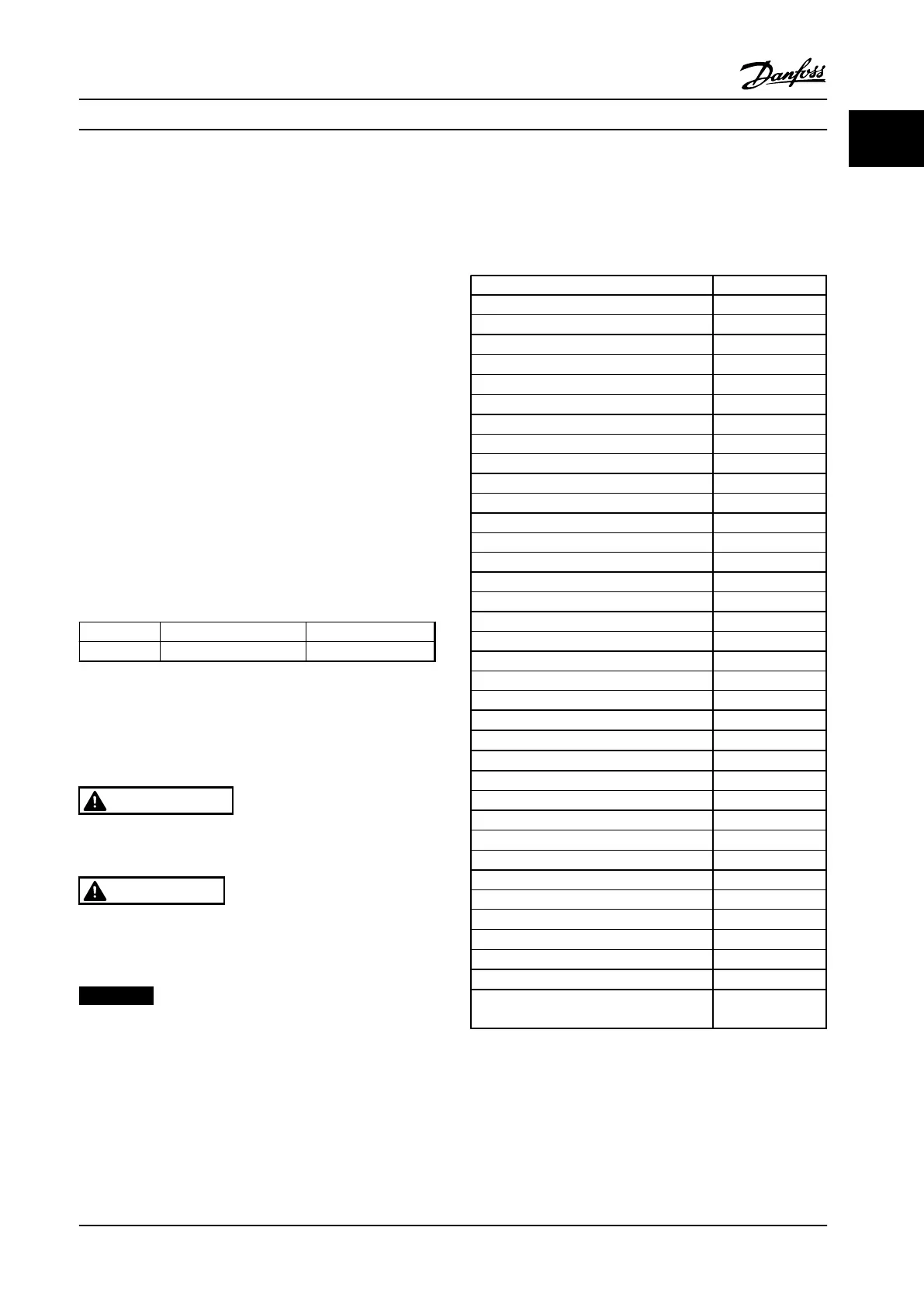
1.4 Abbreviations
Alternating current AC
American wire gauge AWG
Ampere/AMP A
Automatic Motor Adaptation AMA
Current limit I
LIM
Degrees Celsius
°C
Direct current DC
Electro Magnetic Compatibility EMC
Electronic Thermal Relay ETR
Adjustable Frequency Drive FC
Gram g
Hertz Hz
Kilohertz kHz
Local Control Panel LCP
Meter m
Millihenry Inductance mH
Milliampere mA
Millisecond ms
Minute min
Motion Control Tool MCT
Nanofarad nF
Newton Meters Nm
Nominal motor current I
M,N
Nominal motor frequency f
M,N
Nominal motor power P
M,N
Nominal motor voltage U
M,N
Protective Extra Low Voltage PELV
Printed Circuit Board PCB
Rated Inverter Output Current I
INV
Revolutions Per Minute RPM
Regenerative terminals Regen
Second s
Synchronous Motor Speed n
s
Torque limit T
LIM
Volts V
The maximum output current I
DRIVE,MAX
The rated output current supplied by the
adjustable frequency drive
I
DRIVE,N
Table 1.2 Abbreviations
Introduction
Design Guide
MG18C522 Danfoss A/S © Rev. 2014-01-14 All rights reserved. 5
1
1

 Loading...


