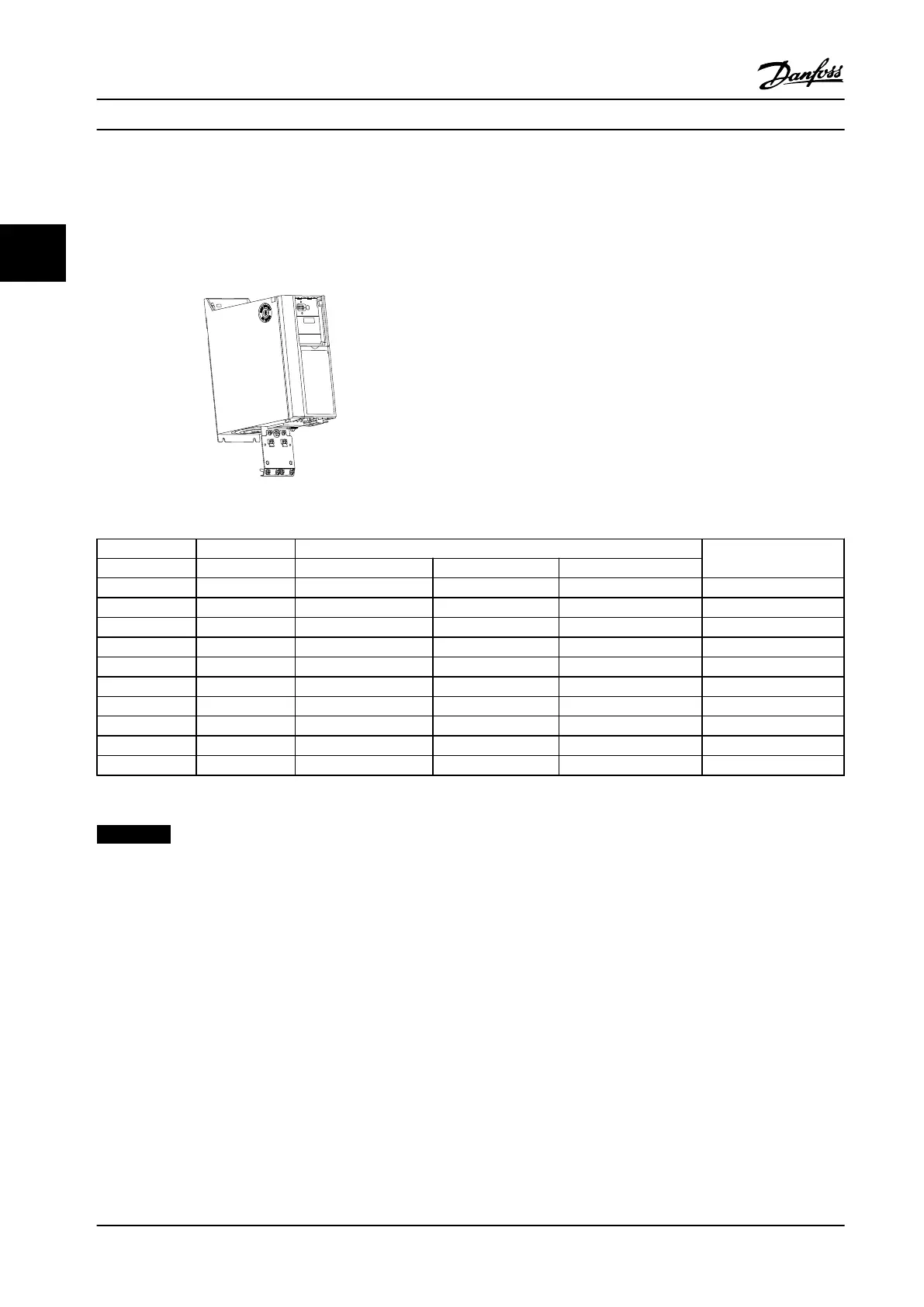
3.1.4 Decoupling Plate
Use the decoupling plate for EMC correct installation.
Shown here on an H3 enclosure.
Figure 3.7 Decoupling Plate
Power (hp [kW]) Decoupling plate
Frame IP class 3 x 200–240 V 3 x 380–480 V 3 x 525–600 V
H1 IP20 0.34–2 [0.25–1.5] 0.5–2 [0.37–1.5] 132B0202
H2 IP20 3 [2.2] 3–5 [2.2–4] 132B0202
H3 IP20 5 [3.7] 7.5–10 [5.5–7.5] 132B0204
H4 IP20 7.5–10 [5.5–7.5] 15–20 [11–15] 132B0205
H5 IP20 15 [11] 25–30 [18.5–22] 130B0205
H6 IP20 20–25 [15–18.5] 40 [30] 25–40 [18.5–30] 132B0207
H6 IP20 50–60 [37–45] 132B0242
H7 IP20 30–40 [22–30] 75 [55] 50–75 [37–55] 132B0208
H7 IP20 100 [75] 132B0243
H8 IP20 50–60 [37–45] 125 [90] 100–125 [75–90] 132B0209
Table 3.4 Decoupling Plate Specifications
NOTICE!
For H9 and H10 adjustable frequency drives, the decoupling plates are included in the accessory bag.
Selection Design Guide
48 Danfoss A/S © Rev. 2014-01-14 All rights reserved. MG18C522
33

 Loading...


