7.11 Danfoss FC Control Profile
7.11.1 Control Word According to FC
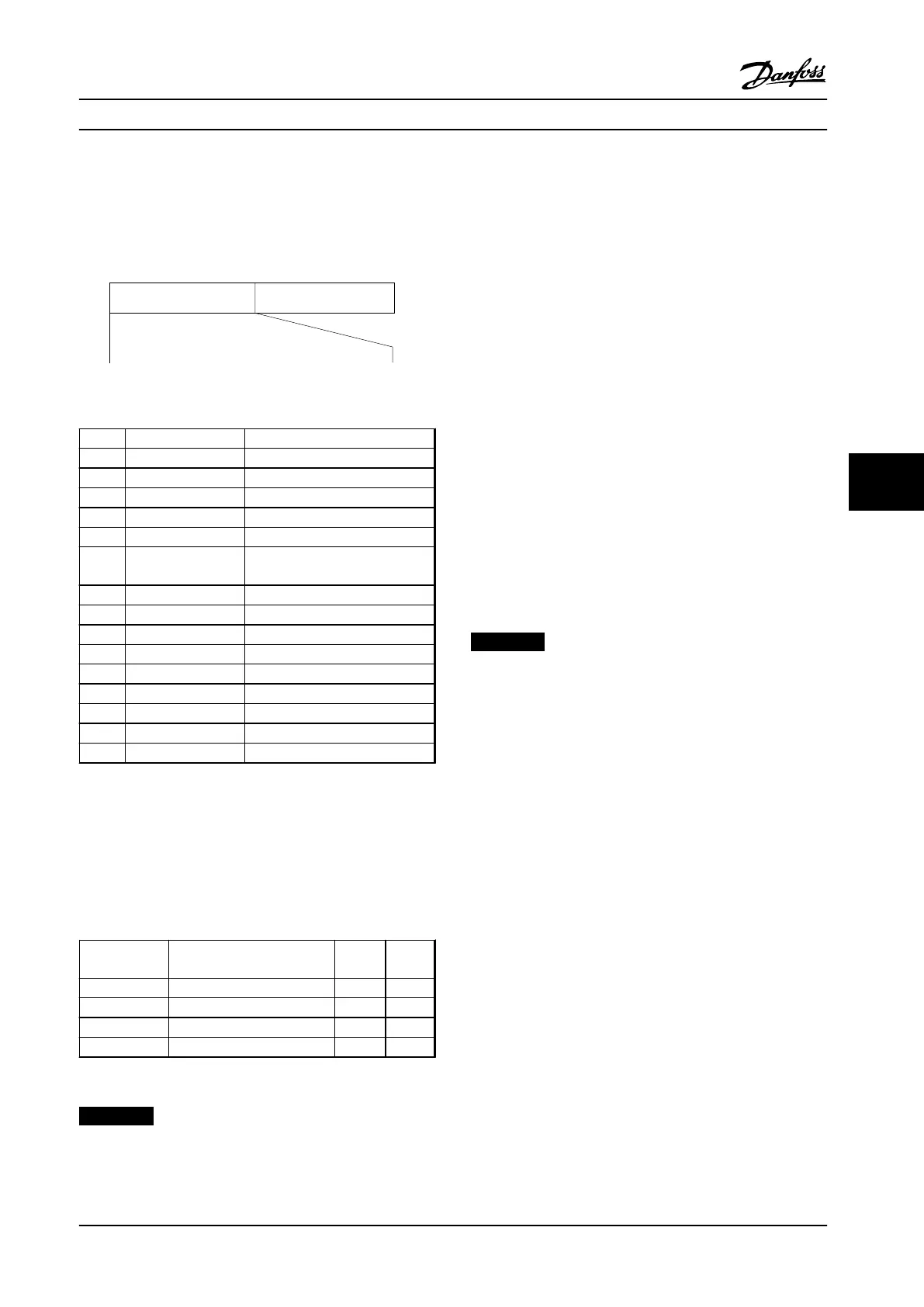
Profile (8-10 Protocol = FC profile)
Speed ref.CTW
Master-follower
130BA274.11
15 14 13 12 11 10 9 8 7 6 5 4 3 2 1 0
Bit
no.:
Figure 7.13 Control Word According to FC Profile
Bit Bit value=0 Bit value=1
00 Reference value external selection lsb
01 Reference value external selection msb
02 DC brake Ramp
03 Coasting No coasting
04 Quick stop Ramp
05 Hold output
frequency
use ramp
06 Ramp stop Start
07 No function Reset
08 No function Jog
09 Ramp 1 Ramp 2
10 Data invalid Data valid
11 Relay 01 open Relay 01 active
12 Relay 02 open Relay 02 active
13 Parameter set-up selection lsb
15 No function Reverse
Table 7.33 Control Word According to FC Profile
Explanation of the control bits
Bits 00/01
Bits 00 and 01 are used to select between the four
reference values, which are pre-programmed in 3-10 Preset
Reference according to the Table 7.34.
Programmed
ref. value
Parameter Bit 01 Bit 00
1
3-10 Preset Reference [0]
0 0
2
3-10 Preset Reference [1]
0 1
3
3-10 Preset Reference [2]
1 0
4
3-10 Preset Reference [3]
1 1
Table 7.34 Control Bits
NOTICE!
Make a selection in 8-56 Preset Reference Select to define
how Bit 00/01 gates with the corresponding function on
the digital inputs.
Bit 02, DC brake
Bit 02=’0’ leads to DC braking and stop. Set braking
current and duration in 2-01 DC Brake Current and 2-02 DC
Braking Time.
Bit 02=’1’ leads to ramping.
Bit 03, Coasting
Bit 03=’0’: The adjustable frequency drive immediately "lets
go" of the motor (the output transistors are "shut off"), and
it coasts to a standstill.
Bit 03=’1’: The adjustable frequency drive starts the motor
if the other starting conditions are met.
Make a selection in 8-50 Coasting Select to define how Bit
03 gates with the corresponding function on a digital
input.
Bit 04, Quick stop
Bit 04=’0’: Makes the motor speed ramp down to stop (set
in 3-81 Quick Stop Ramp Time).
Bit 05, Hold output frequency
Bit 05=’0’: The present output frequency (in Hz) freezes.
Change the frozen output frequency only with the digital
inputs (5-10 Terminal 18 Digital Input to 5-13 Terminal 29
Digital Input) programmed to Speed up=21 and Slow-
down=22.
NOTICE!
If Freeze output is active, the adjustable frequency drive
can only be stopped by the following:
•
Bit 03 Coasting stop
•
Bit 02 DC braking
•
Digital input (5-10 Terminal 18 Digital Input to
5-13 Terminal 29 Digital Input) programmed to
DC braking=5, Coasting stop=2, or Reset and
coasting stop=3.
Bit 06, Ramp stop/start
Bit 06=’0’: Causes a stop and makes the motor speed ramp
down to stop via the selected ramp-down parameter. Bit
06=’1’: Permits the adjustable frequency drive to start the
motor if the other starting conditions are met.
Make a selection in 8-53 Start Select to define how Bit 06
Ramp stop/start gates with the corresponding function on
a digital input.
Bit 07, Reset
Bit 07=’0’: No reset.
Bit 07=’1’: Resets a trip. Reset is activated on the signal’s
leading edge, that is, when changing from logic ’0’ to
logic ’1’.
Bit 08, Jog
Bit 08=’1’: The output frequency is determined by 3-11 Jog
Speed [Hz].
RS-485 Installation and Set...
Design Guide
MG18C522 Danfoss A/S © Rev. 2014-01-14 All rights reserved. 103
7 7

 Loading...


