The master can address individual followers, or can initiate
a broadcast message to all followers. Followers return a
response to queries that are addressed to them
individually. No responses are returned to broadcast
queries from the master. The Modbus RTU protocol
establishes the format for the master’s query by providing
the device (or broadcast) address, a function code defining
the requested action, any data to be sent, and an error-
checking field. The follower’s response message is also
constructed using Modbus protocol. It contains fields
confirming the action taken, any data to be returned and
an error-checking field. If an error occurs in receipt of the
message, or if the follower is unable to perform the
requested action, the follower constructs an error message,
and send it in response, or a timeout occurs.
7.6.4
Adjustable Frequency Drive with
Modbus RTU
The adjustable frequency drive communicates in Modbus
RTU format over the built-in RS-485 interface. Modbus RTU
provides access to the control word and bus reference of
the adjustable frequency drive.
The control word allows the Modbus master to control
several important functions of the adjustable frequency
drive:
•
Start
•
Stop of the adjustable frequency drive in various
ways:
-
Coast stop
-
Quick stop
-
DC Brake stop
-
Normal (ramp) stop
•
Reset after a fault trip
•
Run at a variety of preset speeds
•
Run in reverse
•
Change the active set-up
•
Control the adjustable frequency drive’s built-in
relay
The bus reference is commonly used for speed control. It is
also possible to access the parameters, read their values,
and where possible, write values to them. This permits a
range of control options, including controlling the setpoint
of the adjustable frequency drive when its internal PI
controller is used.
7.7
Network Configuration
To enable Modbus RTU on the adjustable frequency drive,
set the following parameters:
Parameter Setting
8-30 Protocol Modbus RTU
8-31 Address 1-247
8-32 Baud Rate 2400-115200
8-33 Parity / Stop Bits Even parity, 1 stop bit (default)
Table 7.11 Network Configuration
7.8 Modbus RTU Message Framing
Structure
7.8.1 Adjustable Frequency Drive with
Modbus RTU
The controllers are set up to communicate on the Modbus
network using RTU (Remote Terminal Unit) mode, with
each byte in a message containing two 4-bit hexadecimal
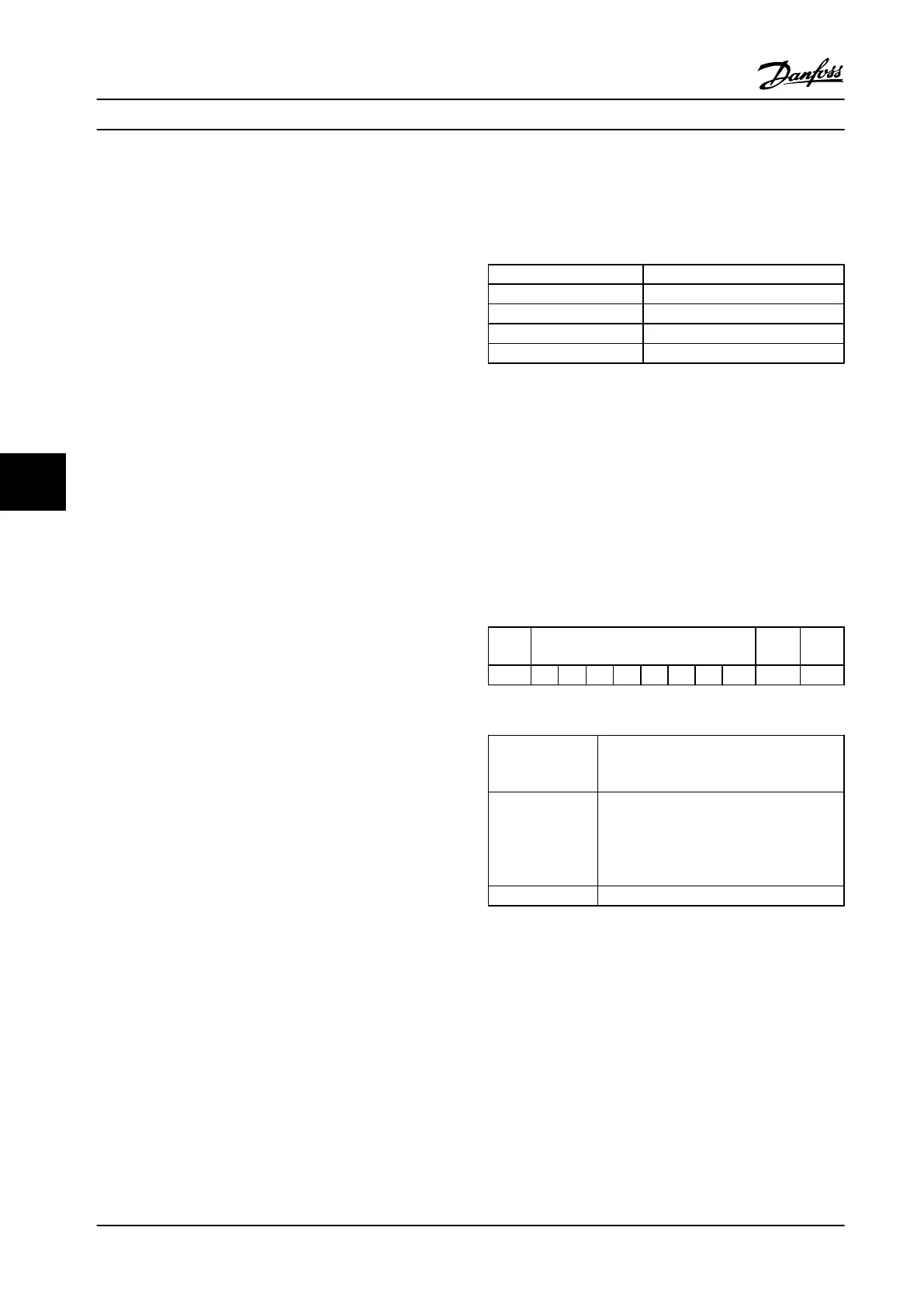
characters. The format for each byte is shown in Table 7.12.
Start
bit
Data byte Stop/
parity
Stop
Table 7.12 Format for Each Byte
Coding System
8-bit binary, hexadecimal 0-9, A-F. 2
hexadecimal characters contained in each 8-
bit field of the message
Bits Per Byte 1 start bit
8 data bits, least significant bit sent first
1 bit for even/odd parity; no bit for no
parity
1 stop bit if parity is used; 2 bits if no parity
Error Check Field Cyclical Redundancy Check (CRC)
RS-485 Installation and Set... Design Guide
94 Danfoss A/S © Rev. 2014-01-14 All rights reserved. MG18C522
77

 Loading...


