1.5 Additional Resources
1.6 Definitions
Adjustable Frequency Drive
I
DRIVE,MAX
The maximum output current.
I
DRIVE,N
The rated output current supplied by the adjustable
frequency drive.
U
DRIVE, MAX
The maximum output voltage.
Input
The connected motor can
start and stop with LCP and
the digital inputs.
Functions are divided into
two groups.
Functions in group 1 have
higher priority than
functions in group 2.
Group
1
Reset, Coasting stop,
Reset and Coasting stop,
Quick Stop, DC braking,
Stop and the [Off] key.
Group
2
Start, Pulse start,
Reversing, Start reversing,
Jog and Freeze output
Table 1.3 Control Commands
Motor
f
JOG
The motor frequency when the jog function is activated
(via digital terminals).
f
M
The motor frequency.
f
MAX
The maximum motor frequency.
f
MIN
The minimum motor frequency.
f
M,N
The rated motor frequency (nameplate data).
I
M
The motor current.
I
M,N
The rated motor current (nameplate data).
n
M,N
The rated motor speed (nameplate data).
P
M,N
The rated motor power (nameplate data).
U
M
The instantaneous motor voltage.
U
M,N
The rated motor voltage (nameplate data).
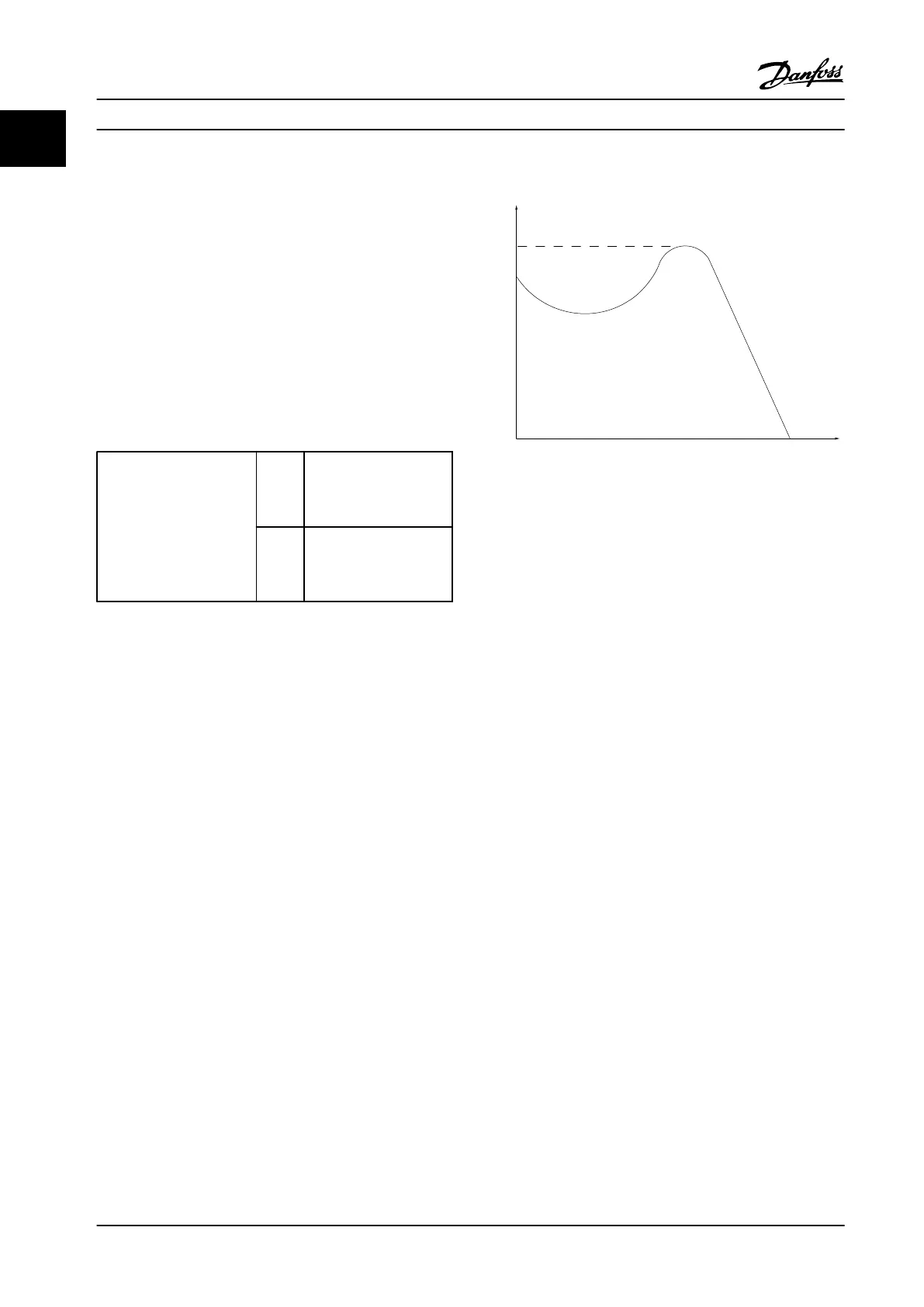
Break-away torque
175ZA078.10
Pull-out
rpm
Torque
Figure 1.1 Break-away torque
η
DRIVE
The efficiency of the adjustable frequency drive is defined
as the ratio between the power output and the power
input.
Start-disable command
A stop command belonging to the group 1 control
commands, see Table 1.3.
Stop command
See Control commands.
References
Analog reference
A signal transmitted to the analog inputs 53 or 54, can be
voltage or current.
Bus reference
A signal transmitted to the serial communication port
(drive port).
Preset reference
A defined preset reference to be set from -100% to +100%
of the reference range. Selection of eight preset references
via the digital terminals.
RefMAX
Determines the relationship between the reference input
at 100% full scale value (typically 10 V, 20 mA) and the
resulting reference. The maximum reference value set in
3-03 Maximum Reference
RefMIN
Determines the relationship between the reference input
at 0% value (typically 0 V, 0 mA, 4 mA) and the resulting
reference. The minimum reference value set in
3-02 Minimum Reference
Introduction
Design Guide
6 Danfoss A/S © Rev. 2014-01-14 All rights reserved. MG18C522
1
1

 Loading...


