7.1.3 Adjustable Frequency Drive Hardware
Set-up
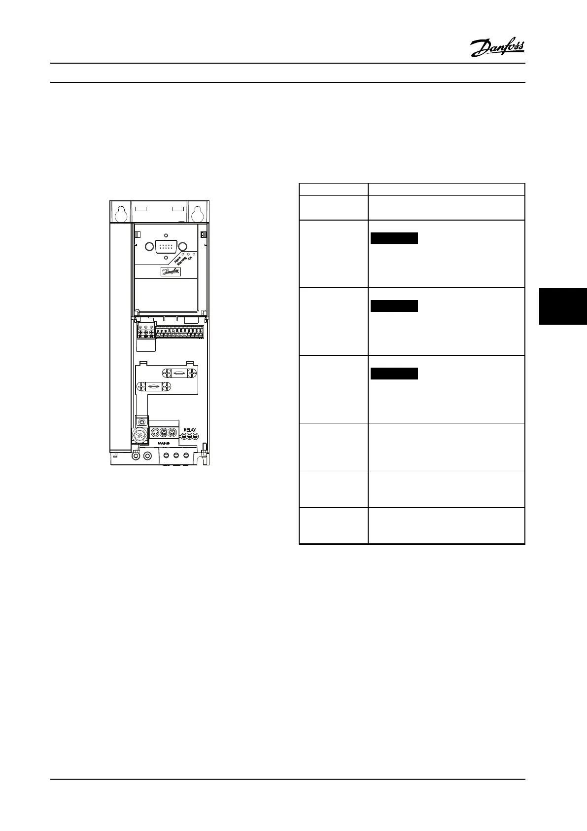
Use the terminator dip switch on the main control board
of the adjustable frequency drive to terminate the RS-485
bus.
Figure 7.2 Terminator Switch Factory Setting
The factory setting for the dip switch is OFF.
7.1.4
Adjustable Frequency Drive
Parameter Settings for Modbus
Communication
Define the RS-485 Communication Set-up
Parameter Function
8-30 Protocol Select the application protocol to run on
the RS-485 interface.
8-31 Address Set the node address.
NOTICE!
The address range depends on the
protocol selected in 8-30 Protocol
8-32 Baud Rate Set the baud rate.
NOTICE!
The default baud rate depends on the
protocol selected in 8-30 Protocol
8-33 Parity / Stop
Bits
Set the parity and number of stop bits.
NOTICE!
The default selection depends on the
protocol selected in 8-30 Protocol
8-35 Minimum
Response Delay
Specify a minimum delay time between
receiving a request and transmitting a
response. This function is for overcoming
modem turnaround delays.
8-36 Maximum
Response Delay
Specify a maximum delay time between
transmitting a request and receiving a
response.
8-37 Maximum
Inter-char delay
If transmission is interrupted, specify a
maximum delay time between two received
bytes to ensure timeout.
Table 7.2 Modbus Communication Parameter Settings
RS-485 Installation and Set... Design Guide
MG18C522 Danfoss A/S © Rev. 2014-01-14 All rights reserved. 87
7 7

 Loading...


