Bit 09, Selection of ramp 1/2
Bit 09="0": Ramp 1 is active (3-41 Ramp 1 Ramp Up Time to
3-42 Ramp 1 Ramp Down Time).
Bit 09="1": Ramp 2 (3-51 Ramp 2 Ramp Up Time to
3-52 Ramp 2 Ramp Down Time) is active.
Bit 10, Data not valid/Data valid
Tell the adjustable frequency drive whether to use or
ignore the control word.
Bit 10=’0’: The control word is ignored.
Bit 10=’1’: The control word is used. This function is
relevant because the message always contains the control
word, regardless of the message type. Turn off the control
word if not wanting to use it when updating or reading
parameters.
Bit 11, Relay 01
Bit 11="0": Relay not activated.
Bit 11="1": Relay 01 activated provided that Control word
bit 11=36 is chosen in 5-40 Function Relay.
Bit 12, Relay 02
Bit 12="0": Relay 02 is not activated.
Bit 12="1": Relay 02 is activated provided that Control word
bit 12=37 is chosen in 5-40 Function Relay.
Bit 13, Selection of set-up
Use bit 13 to select from the two menu set-ups according
to Table 7.35.
Set-up Bit 13
1 0
2 1
The function is only possible when Multi Set-ups=9 is
selected in 0-10 Active Set-up.
Make a selection in 8-55 Set-up Select to define how Bit 13
gates with the corresponding function on the digital
inputs.
Bit 15 Reverse
Bit 15=’0’: No reversing.
Bit 15=’1’: Reversing. In the default setting, reversing is set
to digital in 8-54 Reversing Select. Bit 15 causes reversing
only when Serial communication, Logic or Logic and is
selected.
7.11.2
Status Word According to FC Profile
(STW) (8-30 Protocol = FC profile)
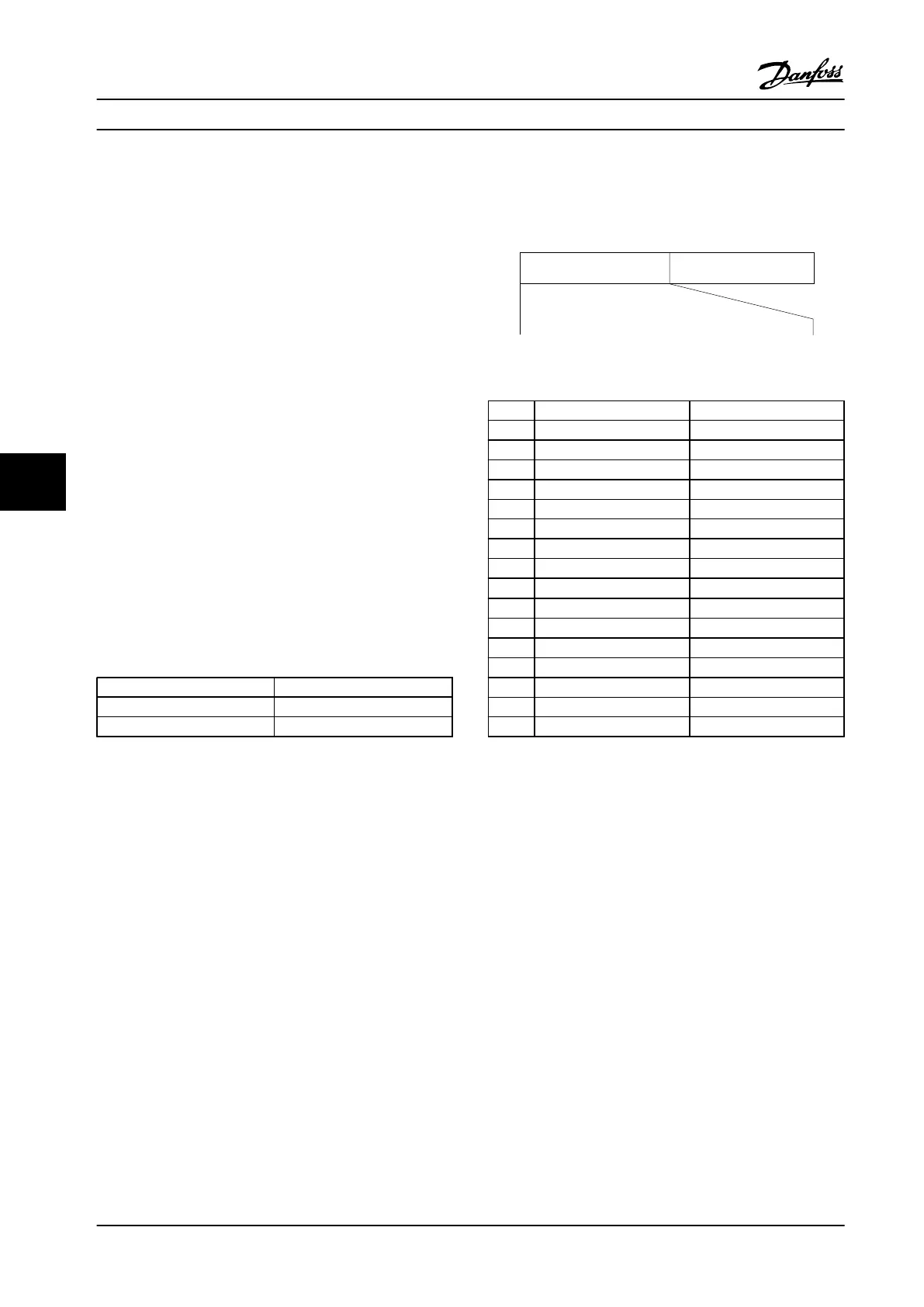
Output freq.STW
Bit
no.:
Follower-master
15 14 13 12 11 10 9 8 7 6 5 4 3 2 1 0
130BA273.11
Figure 7.14 Status Word
Bit Bit=0 Bit=1
00 Control not ready Control ready
01 Drive not ready Drive ready
02 Coasting Enable
03 No error Trip
04 No error Error (no trip)
05 Reserved -
06 No error Triplock
07 No warning Warning
08
Speed ≠ reference
Speed=reference
09 Local operation Bus control
10 Out of frequency limit Frequency limit OK
11 No operation In operation
12 Drive OK Stopped, auto start
13 Voltage OK Voltage exceeded
14 Torque OK Torque exceeded
15 Timer OK Timer exceeded
Table 7.35 Status Word According to FC Profile
Explanation of the status bits
Bit 00, Control not ready/ready
Bit 00=’0’: The adjustable frequency drive trips.
Bit 00=’1’: The adjustable frequency drive controls are
ready, but the power component does not necessarily
receive any power supply (in case of external 24 V supply
to controls).
Bit 01, Drive ready
Bit 01=’0’: The adjustable frequency drive is not ready.
Bit 01=’1’: The adjustable frequency drive is ready for
operation but the coasting command is active via the
digital inputs or via serial communication.
Bit 02, Coasting stop
Bit 02=’0’: The adjustable frequency drive releases the
motor.
Bit 02=’1’: The adjustable frequency drive starts the motor
with a start command.
RS-485 Installation and Set...
Design Guide
104 Danfoss A/S © Rev. 2014-01-14 All rights reserved. MG18C522
77

 Loading...


