Cable length
(ft [m])
AC line voltage [V] Rise time [usec]
V
peak
[kV]
dU/dt [kV/usec]
400 V 90 kW 32.8 [10]
400 0.402 1.108 2.155
400 0.408 1.288 2.529
400 0.424 1.368 2.585
600 V 10 hp [7.5 kW]
16.4 [5] 525 0.192 0.972 4.083
164 [50] 525 0.356 1.32 2.949
16.4 [5] 600 0.184 1.06 4.609
164 [50] 600 0.42 1.49 2.976
Table 8.10
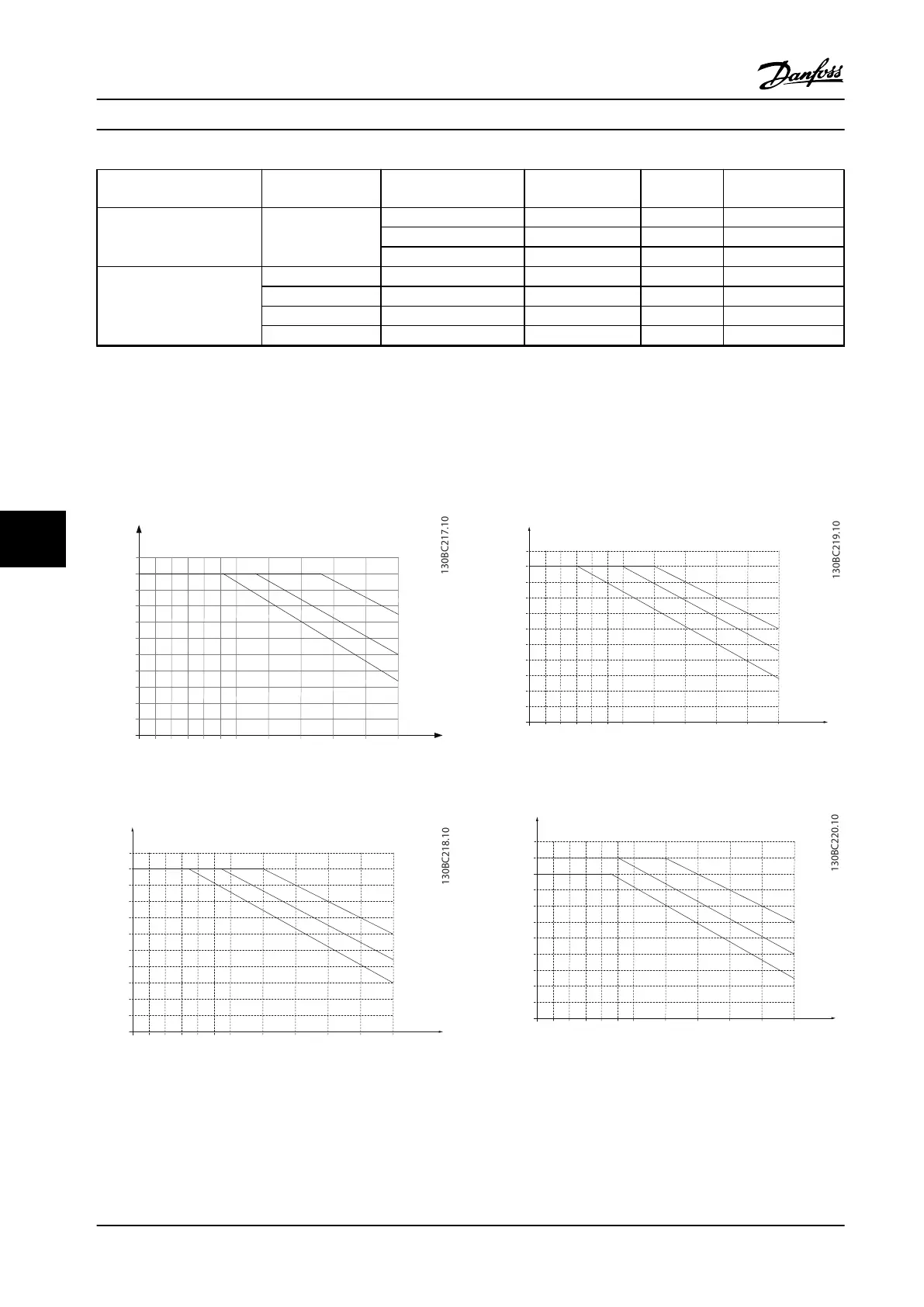
8.5 Derating according to Ambient Temperature and Switching Frequency
The ambient temperature measured over 24 hours should be at least 9 °F [5 °C] lower than the max. ambient temperature.
If the adjustable frequency drive is operated at a high ambient temperature, the continuous output current should be
decreased.
110%
100%
90 %
80
%
70 %
60 %
50 %
40 %
30 %
20 %
10 %
0
I
out
[%]
0
2
5
10
16
40
o
C
50
o
C
45
o
C
fsw[kHz]
Figure 8.1 200 V IP20 H1 0.34–1 hp [0.25–0.75 kW]
fsw [kHz]
20 10
0
10%
20%
30%
40%
50%
60%
70%
80%
90%
100%
110%
I
out [%]
16
40
45
50
5
o
C
o
C
o
C
Figure 8.2 400 V IP20 H1 0.5–2 hp [0.37–1.5 kW]
fsw[kHz]
20 10
0
10%
20%
30%
40%
50%
60%
70%
80%
90%
100%
110%
I
out[%]
16
40
45
50
5
o
C
o
C
o
C
Figure 8.3 200 V IP20 H2 3 hp [2.2 kW]
fsw[kHz]
20 10
0
10%
20%
30%
40%
50%
60%
70%
80%
90%
100%
110%
I
out[%]
16
40
45
50
5
o
C
o
C
o
C
Figure 8.4 400 V IP20 H2 3–5 hp [2.2–4.0 kW]
General Specifications and ... Design Guide
120 Danfoss A/S © Rev. 2014-01-14 All rights reserved. MG18C522
88

 Loading...


