6 How to Program
6.1 Programming with MCT 10 Set-up
Software
The adjustable frequency drive can be programmed from a
PC via RS-485 COM port by using the MCT 10 Set-up
Software. This software can either be ordered using code
number 130B1000 or downloaded from www.danfoss.com/
BusinessAreas/DrivesSolutions/softwaredownload.
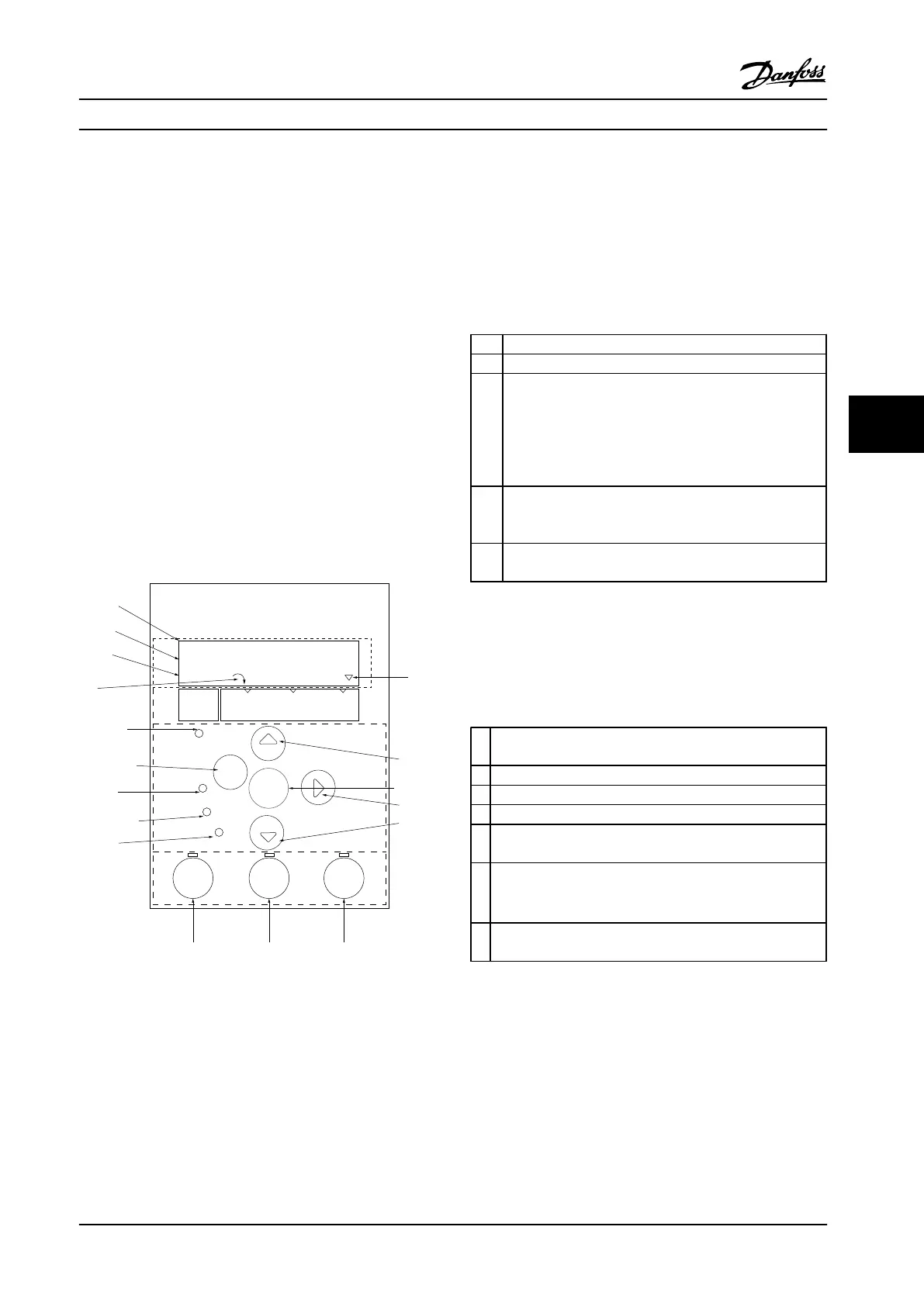
6.2 Local Control Panel (LCP)
The LCP is divided into four functional sections.
A. Display
B. Menu key
C. Navigation keys and LEDs
D. Operation keys and LEDs
130BB765.11
Com.
1-20 Motor Power
[5] 0.37kW - 0.5HP
Setup 1
A
B
1
12
13 14 15
11
11
10
9
8
7
6
5
4
3
2
C
D
Status
Main
Menu
Quick
Menu
Hand
On
OK
Menu
Reset
Auto
On
Alarm
Warn.
On
11
Back
O
Figure 6.1 Local Control Panel (LCP)
A. Display
The LCD display is backlit with two alphanumeric lines. All
data is displayed on the LCP.
Information can be read from the display.
1 Parameter number and name.
2 Parameter value.
3 Set-up number shows the active set-up and the edit set-
up. If the same set-up acts as both the active and edit set-
up, only that set-up number is shown (factory setting).
When active and edit set-up differ, both numbers are
shown in the display (Set-up 12). The flashing number
indicates the edit set-up.
4 Motor direction is shown to the bottom left of the display
– indicated by a small arrow pointing either clockwise or
counter-clockwise.
5 The triangle indicates if the LCP is in status quick menu or
main menu.
Table 6.1 Legend to Figure 6.1
B. Menu key
Press [Menu] to select between status, quick menu or main
menu.
C. Navigation keys and LEDs
6
Com LED: Flashes when bus communication is communi-
cating.
7 Green LED/On: Control section is working.
8 Yellow LED/Warn.: Indicates a warning.
9 Flashing Red LED/Alarm: Indicates an alarm.
10 [Back]: For moving to the previous step or layer in the
navigation structure.
11
[
▲
] [
▼
] [►]: For navigating between parameter groups,
parameters and within parameters. Can also be used for
setting local reference.
12 [OK]: For selecting a parameter and for accepting changes to
parameter settings.
Table 6.2 Legend to Figure 6.1
How to Program Design Guide
MG18C522 Danfoss A/S © Rev. 2014-01-14 All rights reserved. 73
6 6

 Loading...


