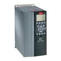
8.1.4 Line Power Supply 3x525–600 V AC
Adjustable frequency drive P2K2 P3K0 P3K7 P5K5 P7K5 P11K P15K P18K P22K P30K P37K P45K P55K P75K P90K
Typical shaft output [kW] 2.2 3.0 3.7 5.5 7.5 11.0 15.0 18.5 22.0 30.0 37 45.0 55.0 75.0 90.0
Typical shaft output [hp] 3.0 4.0 5.0 7.5 10.0 15.0 20.0 25.0 30.0 40.0 50.0 60.0 70.0 100.0 125.0
IP20 frame H9 H9 H9 H9 H9 H10 H10 H6 H6 H6 H7 H7 H7 H8 H8
Max. cable size in terminals
(line power, motor)
[mm
2
/AWG]
4/10 4/10 4/10 4/10 4/10 10/8 10/8 35/2 35/2 35/2 50/1 50/1 50/1 95/0 120/
(4/0)
Output current - 104 °F [40 °C] ambient temperature
Continuous (3 x 525–550 V)
[A]
4.1 5.2 6.4 9.5 11.5 19.0 23.0 28.0 36.0 43.0 54.0 65.0 87.0 105.0 137.0
Intermittent (3 x 525–550 V)
[A]
4.5 5.7 7.0 10.5 12.7 20.9 25.3 30.8 39.6 47.3 59.4 71.5 95.7 115.5 150.7
Continuous (3x551–600 V) [A] 3.9 4.9 6.1 9.0 11.0 18.0 22.0 27.0 34.0 41.0 52.0 62.0 83.0 100.0 131.0
Intermittent (3x551–600 V) [A] 4.3 5.4 6.7 9.9 12.1 19.8 24.2 29.7 37.4 45.1 57.2 68.2 91.3 110.0 144.1
Max. input current
Continuous (3 x 525–550 V)
[A]
3.7 5.1 5.0 8.7 11.9 16.5 22.5 27.0 33.1 45.1 54.7 66.5 81.3 109.0 130.9
Intermittent (3 x 525–550 V)
[A]
4.1 5.6 6.5 9.6 13.1 18.2 24.8 29.7 36.4 49.6 60.1 73.1 89.4 119.9 143.9
Continuous (3x551–600 V) [A] 3.5 4.8 5.6 8.3 11.4 15.7 21.4 25.7 31.5 42.9 52.0 63.3 77.4 103.8 124.5
Intermittent (3x551–600 V) [A] 3.9 5.3 6.2 9.2 12.5 17.3 23.6 28.3 34.6 47.2 57.2 69.6 85.1 114.2 137.0
Max. electrical fuses
See chapter 5.2.3 Fuses and Circuit Breakers
Estimated power loss [W],
best case/typical
1)
65 90 110 132 180 216 294 385 458 542 597 727 1092 1380 1658
Weight enclosure IP54 [kg] 14.6
[6.6]
14.6
[6.6]
14.6
[6.6]
14.6
[6.6]
14.6
[6.6]
25.35
[11.5]
25.35
[11.5]
54.01
[24.5]
54.01
[24.5]
54.01
[24.5]
79.37
[36.0]
79.37
[36.0]
79.37
[36.0]
112.
44
[51.0]
112.
44
[51.0]
Efficiency [%],
best case/typical
1)
97.9 97 97.9 98.1 98.1 98.4 98.4 98.4 98.4 98.5 98.5 98.7 98.5 98.5 98.5
Output current - 122 °F [50 °C] ambient temperature
Continuous (3 x 525–550 V)
[A]
2.9 3.6 4.5 6.7 8.1 13.3 16.1 19.6 25.2 30.1 37.8 45.5 60.9 73.5 95.9
Intermittent (3 x 525–550 V)
[A]
3.2 4.0 4.9 7.4 8.9 14.6 17.7 21.6 27.7 33.1 41.6 50.0 67.0 80.9 105.5
Continuous (3x551–600 V) [A] 2.7 3.4 4.3 6.3 7.7 12.6 15.4 18.9 23.8 28.7 36.4 43.3 58.1 70.0 91.7
Intermittent (3x551–600 V) [A] 3.0 3.7 4.7 6.9 8.5 13.9 16.9 20.8 26.2 31.6 40.0 47.7 63.9 77.0 100.9
Table 8.8 3x525–600 V AC, P2K2–P90K, H6–H10
1) At rated load conditions
General Specifications and ... Design Guide
MG18C522 Danfoss A/S © Rev. 2014-01-14 All rights reserved. 113
8 8

 Loading...


