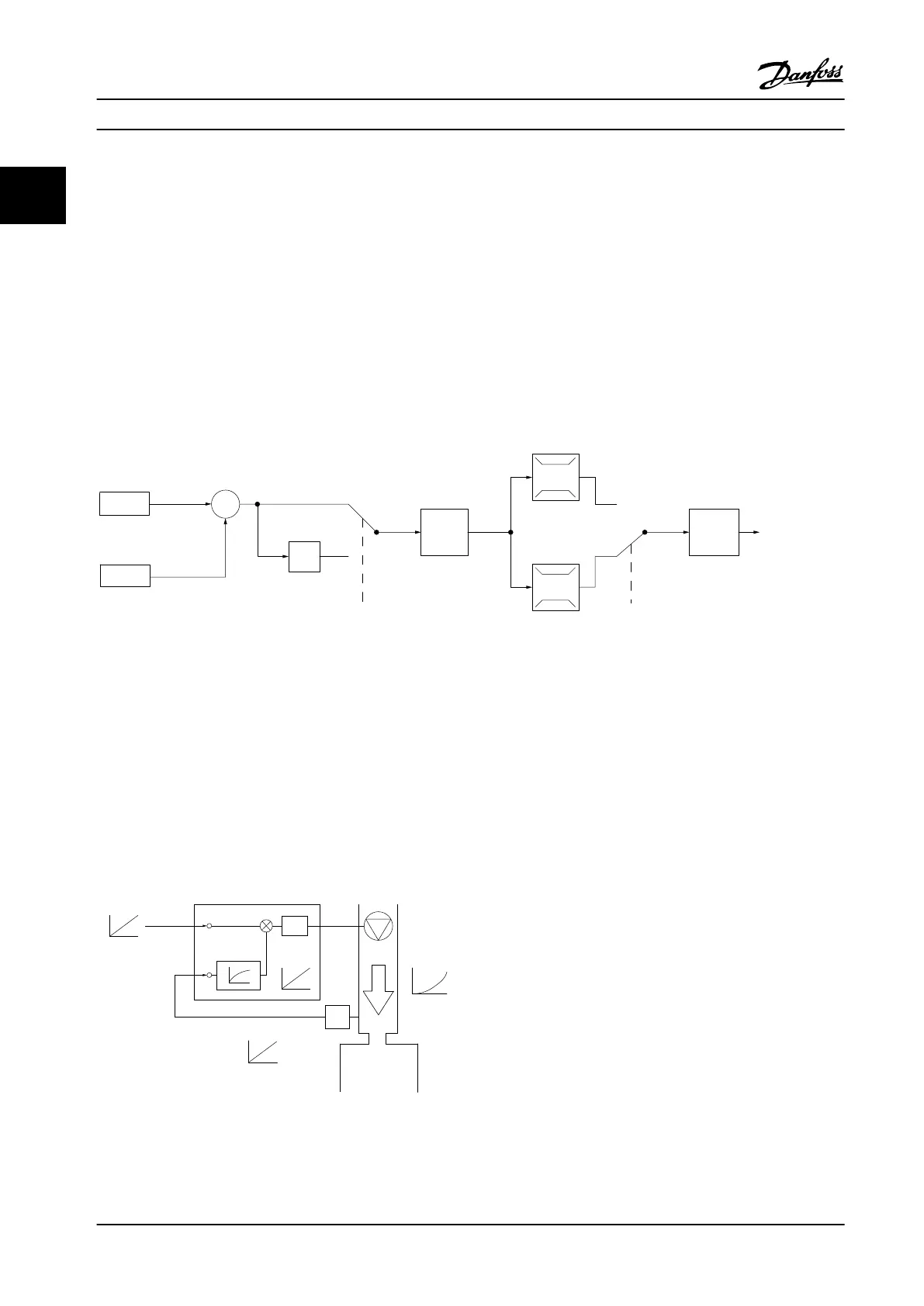
2.7.5 Control Structure Closed-loop
The internal controller allows the adjustable frequency drive to become an integral part of the controlled system. The
adjustable frequency drive receives a feedback signal from a sensor in the system. It then compares this feedback to a
setpoint reference value and determines the error, if any, between these two signals. It then adjusts the speed of the motor
to correct this error.
For example, consider a pump application where the speed of a pump is to be controlled so that the static pressure in a
pipe is constant. The desired static pressure value is supplied to the adjustable frequency drive as the setpoint reference. A
static pressure sensor measures the actual static pressure in the pipe and supplies this to the adjustable frequency drive as
a feedback signal. If the feedback signal is greater than the setpoint reference, the adjustable frequency drive slows down
to reduce the pressure. In a similar way, if the pipe pressure is lower than the setpoint reference, the adjustable frequency
drive automatically speed up to increase the pressure provided by the pump.
7-30 PI
Normal/Inverse
Control
PI
Reference
Feedback
Scale to
speed
P 4-10
Motor speed
direction
To motor
control
130BB894.11
S
100%
0%
-100%
100%
*[-1]
_
+
Figure 2.19 Control Structure Closed-loop
While the default values for the adjustable frequency drive’s closed-loop controller often provides satisfactory performance,
the control of the system can often be optimized by adjusting some of the closed-loop controller’s parameters.
2.7.6
Feedback Conversion
In some applications, it may be useful to convert the feedback signal. One example of this is using a pressure signal to
provide flow feedback. Since the square root of pressure is proportional to flow, the square root of the pressure signal
yields a value proportional to the flow. See Figure 2.20.
130BB895.10
+
-
PI
P
P
P
Ref.
signal
Desired
ow
FB conversion
Ref.
FB
Flow
FB
signal
Flow
P 20-01
Figure 2.20 Feedback Signal Conversion
Product Overview Design Guide
28 Danfoss A/S © Rev. 2014-01-14 All rights reserved. MG18C522
22

 Loading...


