Provided that the short-circuit power of the supply S
sc
is
greater than or equal to:
S
SC
= 3 ×
R
SCE
×
U
line power
×
I
equ
= 3 × 120 × 400 ×
I
equ
at the interface point between the user’s supply and the
public system (R
sce
).
It is the responsibility of the installer or user of the
equipment to ensure, by consultation with the distribution
network operator if necessary, that the equipment is
connected only to a supply with a short-circuit power S
sc
greater than or equal to that specified above.
Other power sizes can be connected to the public supply
network by consultation with the distribution network
operator.
Compliance with various system level guidelines:
The harmonic current data in Table 2.15 to Table 2.22 are
given in accordance with IEC/EN 61000-3-12 with reference
to the Power Drive Systems product standard. They may
be used as the basis for calculation of the harmonic
currents' influence on the power supply system and for the
documentation of compliance with relevant regional
guidelines: IEEE 519 -1992; G5/4.
2.8.6
Immunity Requirements
The immunity requirements for adjustable frequency drives
depend on the environment where they are installed. The
requirements for the industrial environment are higher
than the requirements for the home and office
environment. All Danfoss adjustable frequency drives
comply with the requirements for the industrial
environment and consequently comply also with the lower
requirements for home and office environment with a
large safety margin.
2.9
Galvanic Isolation (PELV)
2.9.1 PELV - Protective Extra Low Voltage
PELV offers protection by way of extra low voltage.
Protection against electric shock is ensured when the
electrical supply is of the PELV type and the installation is
made as described in local/national regulations on PELV
supplies.
All control terminals and relay terminals 01-03/04-06
comply with PELV (Protective Extra Low Voltage) (Does not
apply to grounded Delta leg above 440 V).
Galvanic (ensured) isolation is obtained by fulfilling
requirements for higher isolation and by providing the
relevant creepage/clearance distances. These requirements
are described in the EN 61800-5-1 standard.
The components that make up the electrical isolation, as
described, also comply with the requirements for higher
isolation and the relevant test as described in EN
61800-5-1.
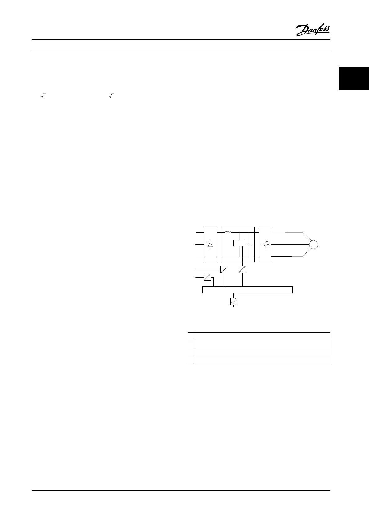
The PELV galvanic isolation can be shown in Figure 2.26.
To maintain PELV all connections made to the control
terminals must be PELV, e.g., thermistor must be
reinforced/double insulated.
0.25–22 kW
Figure 2.25 Galvanic Isolation
1 Power supply (SMPS)
2 Optocouplers, communication between AOC and BOC
3 Custom relays
a Control card terminals
Table 2.23 Legend to Figure 2.25
Product Overview Design Guide
MG18C522 Danfoss A/S © Rev. 2014-01-14 All rights reserved. 41
2 2

 Loading...


