NOTICE!
Some of the harmonic currents might disturb communi-
cation equipment connected to the same transformer or
cause resonance in connection with power-factor
correction batteries.
To ensure low harmonic currents, the adjustable frequency
drive is equipped with intermediate circuit coils as
standard. This normally reduces the input current I
RMS
by
40%.
The voltage distortion on the line power supply voltage
depends on the size of the harmonic currents multiplied
by the line power impedance for the frequency in
question. The total voltage distortion THD is calculated on
the basis of the individual voltage harmonics using this
formula:
THD
% =
U
2
5
+
U
2
7
+ ... +
U
2
N
(U
N
% of U)
2.8.4
Harmonics Emission Requirements
Equipment connected to the public supply network
Options Definition
1 IEC/EN 61000-3-2 Class A for 3-phase balanced
equipment (for professional equipment only up to 1
kW total power).
2 IEC/EN 61000-3-12 Equipment 16 A-75 A and profes-
sional equipment as from 1 kW up to 16 A phase
current.
Table 2.14 Connected Equipment
2.8.5
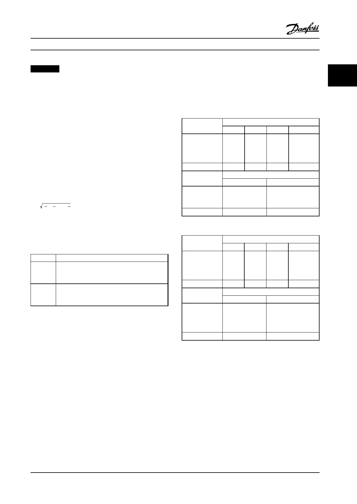
Harmonics Test Results (Emission)
Power sizes up to PK75 in T4 and P3K7 in T2 complies with
IEC/EN 61000-3-2 Class A. Power sizes from P1K1 and up to
P18K in T2 and up to P90K in T4 complies with IEC/EN
61000-3-12, Table 4.
Individual Harmonic Current I
n
/I
1
(%)
I
5
I
7
I
11
I
13
Actual 0.34–15
hp [0.25–11 kW],
IP20, 200 V
(typical)
32.6 16.6 8.0 6.0
Limit for R
sce
≥120
40 25 15 10
Harmonic current distortion factor (%)
THD PWHD
Actual 0.34–15
hp [0.25–11 kW],
200 V (typical)
39 41.4
Limit for R
sce
≥120
48 46
Table 2.15 Harmonic Current 0.34–15 hp [0.25–11 kW], 200 V
Individual Harmonic Current I
n
/I
1
(%)
I
5
I
7
I
11
I
13
Actual 0.5–30 hp
[0.37–22 kW],
IP20, 380–480 V
(typical)
36.7 20.8 7.6 6.4
Limit for R
sce
≥120
40 25 15 10
Harmonic current distortion factor (%)
THD PWHD
Actual 0.5–30 hp
[0.37–22 kW],
380–480 V
(typical)
44.4 40.8
Limit for R
sce
≥120
48 46
Table 2.16 Harmonic Current 0.5–30 hp [0.37–22 kW],
380–480 V
Product Overview Design Guide
MG18C522 Danfoss A/S © Rev. 2014-01-14 All rights reserved. 39
2 2

 Loading...


