4.1.19 Motor Connection for C3 and C4
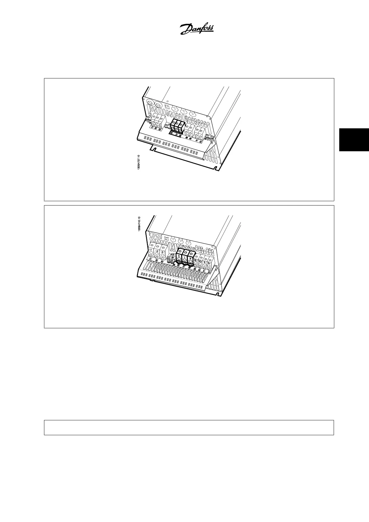
Figure 4.25: First terminate the motor ground, then place motor U, V and W wires into the appropriate terminals and tighten. Please ensure
that the outer insulation of the motor cable is removed under the EMC clamp.
Figure 4.26: First terminate the motor ground, then place motor U, V and W wires into the appropriate terminals and tighten. Please ensure
that the outer insulation of the motor cable is removed under the EMC clamp.
4.1.20 Wiring Example and Testing
The following section describes how to terminate and access control wires. For an explanation of the function, programming and wiring of the control
terminals, please see chapter
How to program the adjustable frequency drive.
4.1.21 DC Bus Connection
The DC bus terminal is used for DC backup, with the intermediate circuit being supplied from an external source.
Terminal numbers used: 88, 89
VLT
®
HVAC Drive Instruction Manual 4 Electrical Installation
MG.11.AB.22 - VLT
®
is a registered Danfoss trademark
4-21
4