Parameter [Units]
Par. 0-01
Language
Par. 1-20
Motor Power [kW]
[kW]
Par. 1-21
Motor Power [HP]
[HP]
Par. 1-22
Motor Voltage
*[V]
Par. 1-23
Motor Frequency
[Hz]
Par. 1-24
Motor Current
[A]
Par. 1-25
Motor Nominal Speed
[RPM]
Par. 1-28
Motor Rotation Check
[Hz]
Par. 3-41
Ramp 1 Ramp-up Time
[s]
Par. 3-42
Ramp 1 Ramp-down Time
[s]
Par. 4-11
Motor Speed Low Limit [RPM]
[RPM]
Par. 4-12
Motor Speed Low Limit [Hz]
*[Hz]
Par. 4-13
Motor Speed High Limit [RPM]
[RPM]
Par. 4-14
Motor Speed High Limit [Hz]
*[Hz]
Par. 3-19
Jog Speed [RPM]
[RPM]
Par. 3-11
Jog Speed [Hz]
*[Hz]
Par. 5-12
Terminal 27 Digital Input
Par. 5-40
Function Relay
**
Table 5.1: Quick Set-up parameters
*The display showing depends on choices made in par. 0-02
Motor Speed Unit
and par. 0-03
Regional Settings
. The default settings of par. 0-02
Motor
Speed Unit
and par. 0-03
Regional Settings
depend on which region of the world the adjustable frequency drive is supplied to but can be re-programmed
as required.
** Par. 5-40
Function Relay
, is an array, where one may choose between Relay1 [0] or Relay2 [1]. Standard setting is Relay1 [0] with the default choice
Alarm [9].
See the parameter description in the section
Commonly Used Parameters
.
For a detailed information about settings and programming, please see the
VLT HVAC Drive Programming Guide, MG.11.CX.YY
x=version number y=language
NOTE!
If [No Operation] is selected in par. 5-12
Terminal 27 Digital Input
, no connection to +24 V on terminal 27 is necessary to enable start.
If [Coast Inverse] (factory default value) is selected in par. 5-12
Terminal 27 Digital Input
, a connection to +24 V is necessary to enable
start.
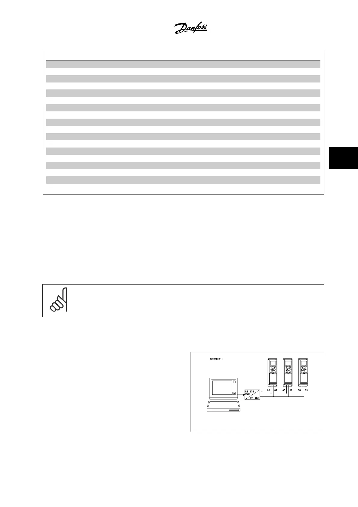
5.1.2 RS-485 Bus Connection
One or more adjustable frequency drives can be connected to a controller
(or master) using the standard RS-485 interface. Terminal 68 is connec-
ted to the P signal (TX+, RX+), while terminal 69 is connected to the N
signal (TX-, RX-).
If more than one adjustable frequency drive is connected to a master,
use parallel connections.
Figure 5.2: Connection example.
VLT
®
HVAC Drive Instruction Manual 5 Commissioning and Application Examples
MG.11.AB.22 - VLT
®
is a registered Danfoss trademark
5-3
5

 Loading...


