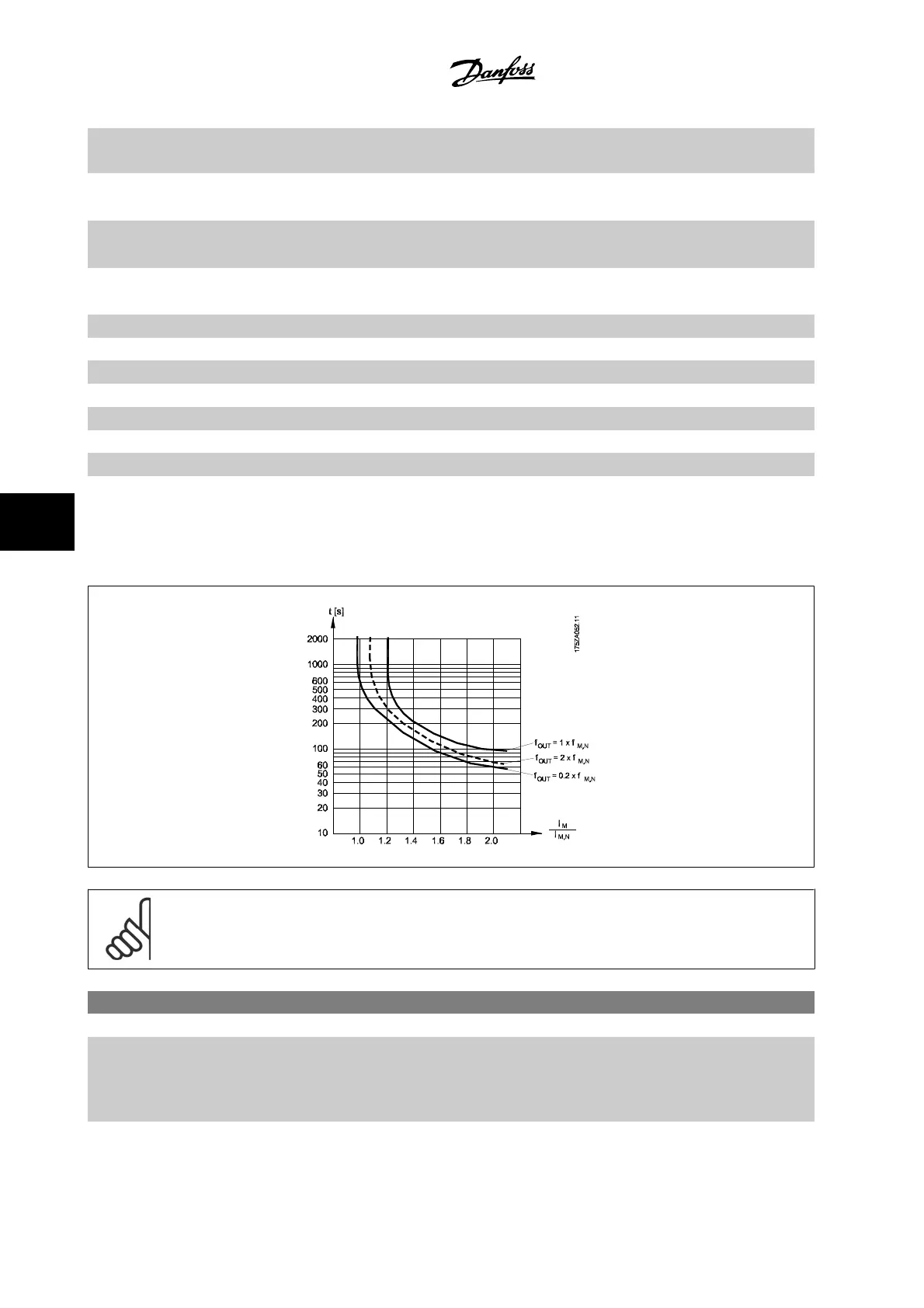
I
M,N
and the rated motor frequency f
M,N
. The calculations estimate the need for a lower
load at lower speed due to less cooling from the fan incorporated in the motor.
[0] No protection If the motor is continuously overloaded and no warning or trip of adjustable frequency drive is
wanted.
[1] Thermistor warning Activates a warning when the connected thermistor in the motor reacts in the event of motor over-
temperature.
[2] Thermistor trip Stops (trips) the adjustable frequency drive when the connected thermistor in the motor reacts in
the event of motor overtemperature.
[3] ETR warning 1
[4] * ETR trip 1
[5] ETR warning 2
[6] ETR trip 2
[7] ETR warning 3
[8] ETR trip 3
[9] ETR warning 4
[10] ETR trip 4
ETR (Electronic Thermal Relay) functions 1-4 will calculate the load when the set-up where they were selected is active. For example, ETR-3 starts
calculating when Set-up 3 is selected. For the North American market: The ETR functions provide class 20 motor overload protection in accordance with
NEC.
NOTE!
Danfoss recommends using 24 VDC as thermistor supply voltage.
1-93 Thermistor Source
Option: Function:
Select the input to which the thermistor (PTC sensor) should be connected. An analog input option
[1] or [2] cannot be selected if the analog input is already in use as a reference source (selected in
par. 3-15
Reference 1 Source
, par. 3-16
Reference 2 Source
or par. 3-17
Reference 3 Source
).
When using MCB112, choice [0]
None
must always be selected.
7 How to Program the Adjustable Frequency
Drive
VLT
®
HVAC Drive Instruction Manual
7-18
MG.11.AB.22 - VLT
®
is a registered Danfoss trademark
7
 Loading...


