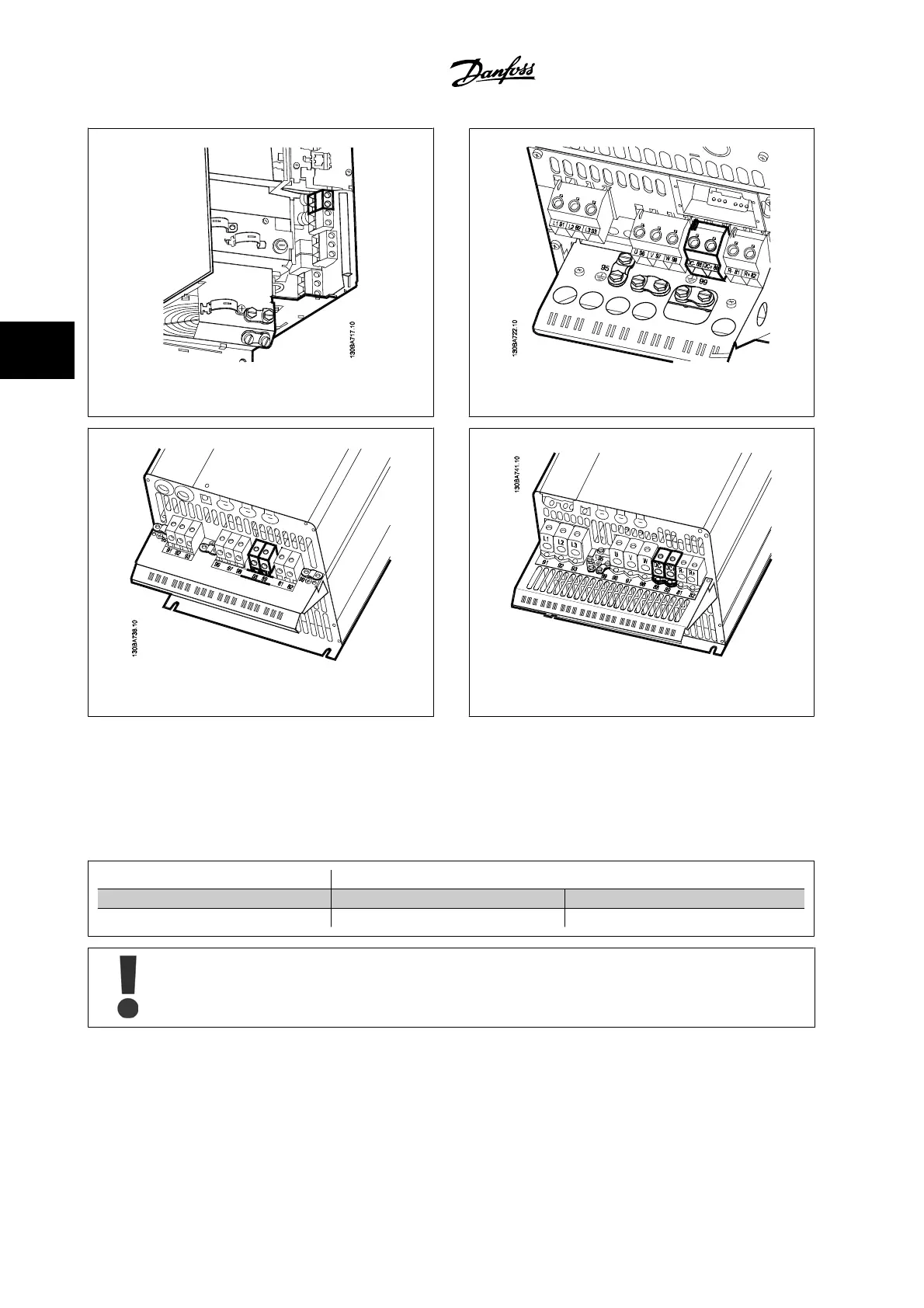
Figure 4.27: DC bus connections for enclosure B3. Figure 4.28: DC bus connections for enclosure B4.
Figure 4.29: DC bus connections for enclosure C3. Figure 4.30: DC bus connections for enclosure C4.
Please contact Danfoss if you require further information.
4.1.22 Brake Connection Option
The connection cable to the brake resistor must be shielded/armored.
Brake resistor
Terminal number 81 82
Terminals R- R+
Dynamic brake calls for extra equipment and safety considerations. For further information, please contact Danfoss.
1. Use cable clamps to connect the shield to the metal cabinet of the adjustable frequency drive and to the decoupling plate of the brake resistor.
2. Dimension the cross-section of the brake cable to match the brake current.
4 Electrical Installation VLT
®
HVAC Drive Instruction Manual
4-22
MG.11.AB.22 - VLT
®
is a registered Danfoss trademark
4