4.1.26 Control Terminals
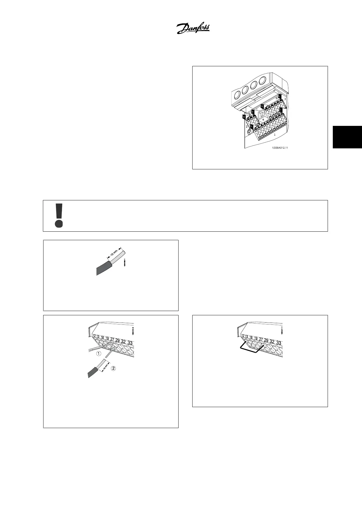
Drawing reference numbers:
1. 10-pole plug digital I/O.
2. 3-pole plug RS-485 bus.
3. 6-pole analog I/O.
4. USB connection.
Figure 4.41: Control terminals (all enclosures)
4.1.27 How to Test Motor and Direction of Rotation
Note that unintended motor start can occur; make sure no personnel or equipment is in danger!
Figure 4.42:
Step 1: First, remove the insulation on both ends of a 1.97–
2.76 in [50–70 mm] piece of wire.
Please follow these steps to test the motor connection and direction of
rotation. Start with no power to the unit.
Figure 4.43:
Step 2: Insert one end in terminal 27 using a suitable ter-
minal screwdriver. (Note: For units with the Safe Stop func-
tion, the existing jumper between terminal 12 and 37 should
not be removed for the unit to be able to run!)
Figure 4.44:
Step 3: Insert the other end in terminal 12 or 13. (Note:
For units with the Safe Stop function, the existing jumper
between terminal 12 and 37 should not be removed for the
unit to be able to run!)
VLT
®
HVAC Drive Instruction Manual 4 Electrical Installation
MG.11.AB.22 - VLT
®
is a registered Danfoss trademark
4-29
4