Voltages up to 975 V DC (@ 600 V AC) may occur between the terminals.
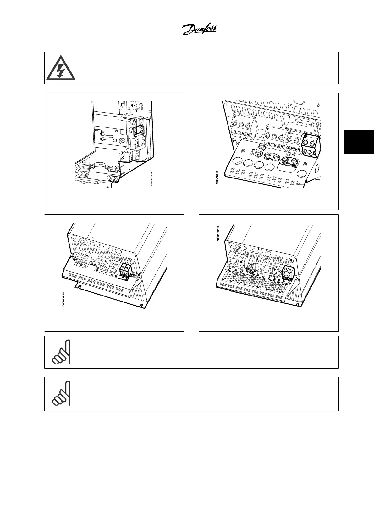
Figure 4.31: Brake connection terminal for B3. Figure 4.32: Brake connection terminal for B4.
Figure 4.33: Brake connection terminal for C3. Figure 4.34: Brake connection terminal for C4.
NOTE!
If a short circuit in the brake IGBT occurs, prevent power dissipation in the brake resistor by using a line switch or contactor to disconnect
the line power from the adjustable frequency drive. Only the adjustable frequency drive should control the contactor.
NOTE!
Place the brake resistor in an environment free of fire risk and ensure that no external objects can fall into the brake resistor through
ventilation slots.
Do not cover ventilation slots and grids.
VLT
®
HVAC Drive Instruction Manual 4 Electrical Installation
MG.11.AB.22 - VLT
®
is a registered Danfoss trademark
4-23
4