TRIGGER, POSITIONING AND FOCUSING DEVICE SETUP
278
AV500/AV900 2D CAMERA
13. In e-Genius under Diagnostics, navigate to Serial Comm Status. The Serial Com-
munications Status window opens.
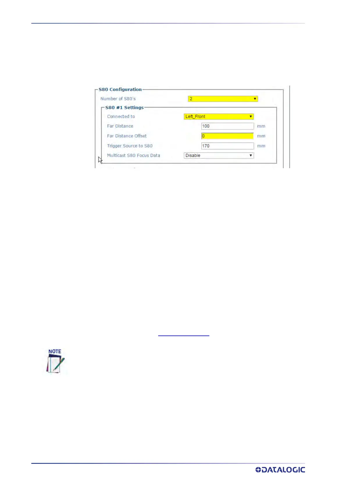
14. Determine the Far Distance (A).
15. Enter the displayed distance in the Operating Mode > F
ar Distance field. Click
Update to save your changes.
16. Remove all objects from the conveyor belt and click the Start button.
17. Place an object of known width on the far edge of the conveyor and adjust the Far
Distance Of
fset (B) until the focus value equals the object width.
18. To adjust the distance, press enter each time you mak
e an adjustment.
19. Enter this displayed value in the Operating Mode
> Far Distance Offset field.
20. Click Update to sa
ve your changes.
SETTING UP THE DM3610 DIMENSIONER
This focus setup is used to calibrate Dimensioner system focus data for AV500/AV900
Camera systems. DM3610 Dimensioners provide focus data for Datalogic cameras,
including the camera, NVS9000, and AV6010.
Refer to the DM3610 Dimensioner Reference Manual (or Two-Head Dimensioner
Refer-
ence Manual) for complete information on installation
and calibration of the DM3610. It
is available for download from
www.datalogic.com.
Also see “AV500 Timing and Distance Diagrams” on page 355.
For single Dimensioner applications, the DM3610 must be running software version
1.8.11 or greater. For multi-head applications, the DM3610’s must be running 1.8.1 and
the DC3000 must be version 1.3.60 or greater.
The Dimensioner scan line must be installed at least 500 mm [20 in] upstream from the
nearest camera scan line.
The examples used in this guide use Imperial units i.e. inches. AV500/AV900 If the sys-
tem is configured for metric, the unit of measure will be in mm.
Remember to reset these parameters to the application specifications after the calibra-
tion is complete.