TRIGGER AND FOCUSING DEVICE WIRING
PRODUCT REFERENCE GUIDE
67
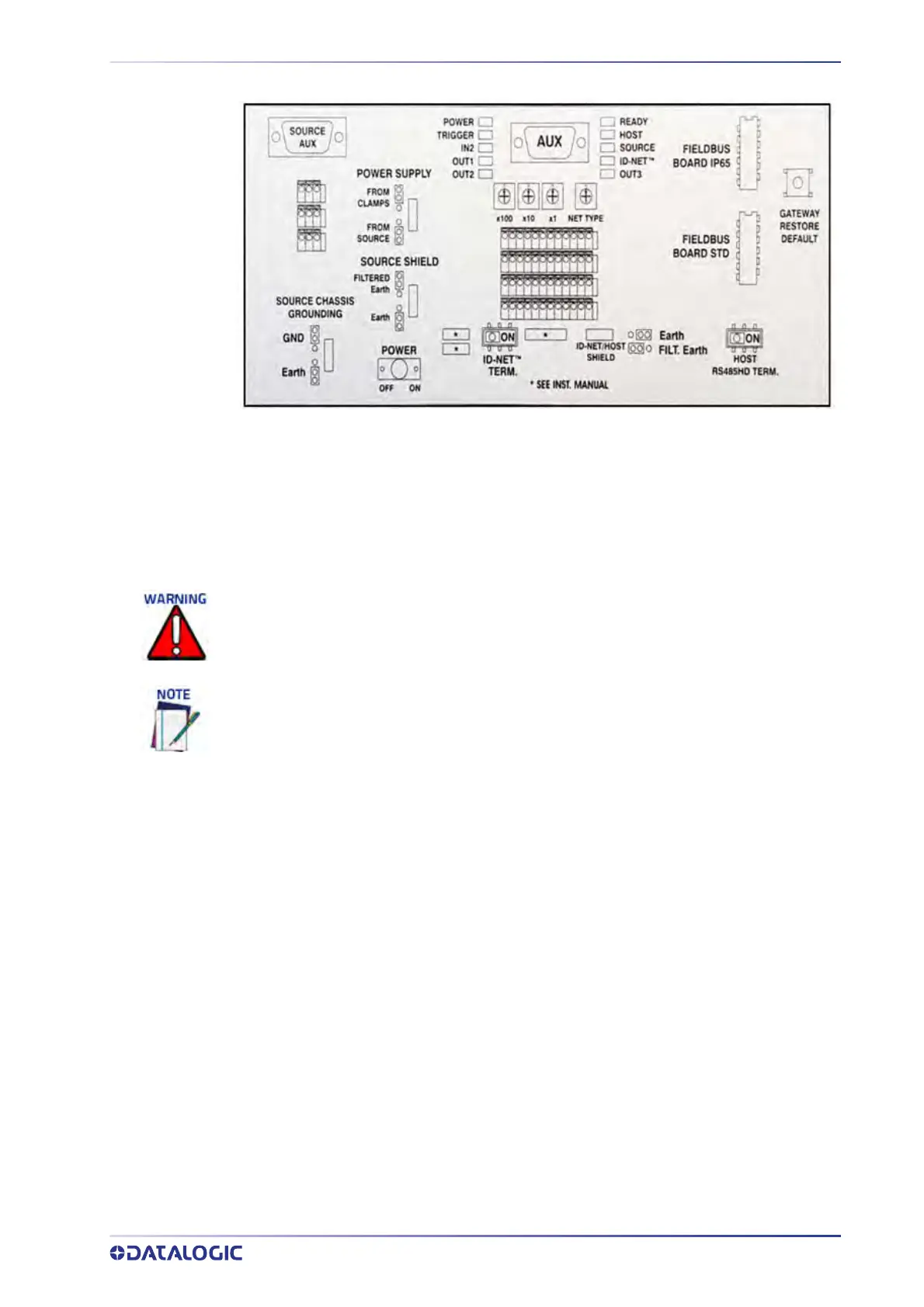
Box Interior Diagram
Photoelectric Sensor Connections to CBX100/800
Barcode scanning applications may use a Datalogic photoelectric sensor as a trigger
device. The photoelectric sensor is wired directly into the CBX100/800 terminal block.
If your application uses a trigger other than the one specified b
y Datalogic, follow the
appropriate wiring diagram to assure proper wiring.
The following diagrams illustrate standard recommended wiring of the Photoelectric
Sensor to the CBX100/800 terminal block.
You must use shielded interface cables with this product. To maintain FCC compliance,
the cable shield must make a 360-degree connection to the shielded mating connector.
To confirm the photoelectric sensor is functioning properly, watch the TRIGGER LED first
in the CBX and also on the camera while the photoelectric sensor’s beam is blocked. The
Datalogic photoelectric sensor also includes a status LED.