MATRIX 210N™ REFERENCE MANUAL
OUTPUTS
Two opto-coupled general purpose outputs are available on the 25-pin connector. See par. 0
for more details.
The pinout is the following:
Power Supply input voltage +
Configurable digital output 1 - positive pin
Configurable digital output 1 - negative pin
Configurable digital output 2 - positive pin
Configurable digital output 2 - negative pin
Power Supply input voltage -
The electrical features of the two outputs are the following:
V
Out
(I
Load
= 0 mA) max = 30 Vdc.
V
Out
(I
Load
= 10 mA) max = 1.8 Vdc
I
Load
max = 40 mA continuous; 130 mA pulsed
P
D
= V
Out
I
Load
max = 170 mW
The output signals are fully programmable being determined by the configured
Activation/Deactivation events, Deactivation Timeout or a combination of the two. For further
details refer to the Help On Line page for the Output Setup step in DL.CODE.
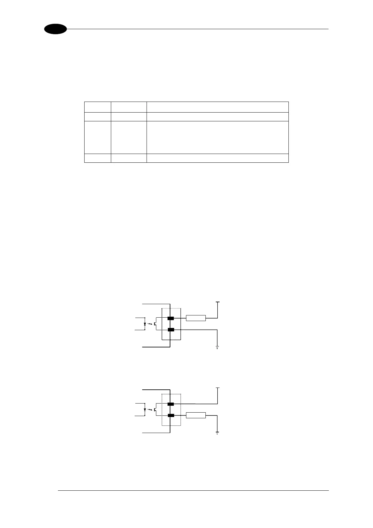
Figure 91 – Isolated Current Sinking Output Connection
Figure 92 – Isolated Current Sourcing Output Connection