TYPICAL LAYOUTS
5 TYPICAL LAYOUTS
The following typical layouts refer to system hardware configurations. However, they also
require the correct setup of the software configuration parameters. Dotted lines in the figures
refer to optional hardware configurations within the particular layout.
NOTE: All software configurations are made through DL.CODE which
connects to the reader through the on-board Ethernet interface.
NOTE: DL.CODE now supports several different multi device configuration
types using the PASS-THROUGH configuration. In particular this feature
allows MULTIDATA ID-NET network configurations to be made. Master/Slave
SYNCHRONIZED ID-NET network configurations are also configurable as
before.
NOTE: The Master/Slave Role is only significant for the Internal ID-NET
Network. If your layout doesn’t use the ID-NET network then the device’s Role
is not significant and can be ignored.
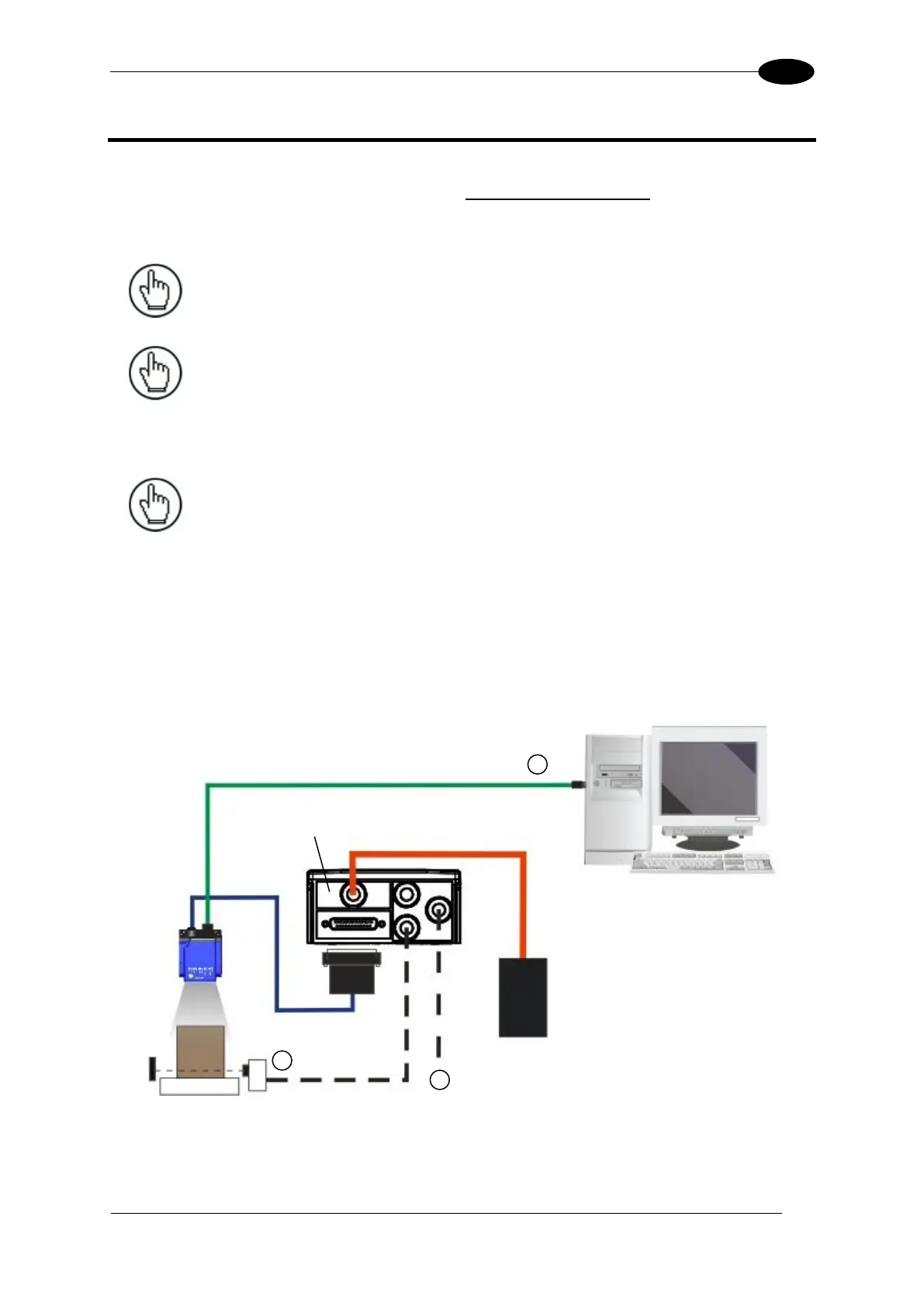
5.1 ETHERNET CONNECTION
The Ethernet connection is possible in two different layouts.
In a Point-to-Point layout the reader is connected to a local host by using a CAB-ETH-M0x
cable. There is no need to use a crossover adapter since Matrix 210N incorporates an auto-
cross function.
Figure 62 - Ethernet Point-to-Point Layout
All devices always support multiple output channels (i.e. for data monitoring).
Ethernet Interface
Auxiliary Serial Interface (RS232 – Data Monitor)
External Trigger (for One Shot or Phase Mode)