Register map register file 0x24 is for control of the DW1000 synchronisation hardware.
There is a separate application note giving details of the external synchronisation. Please consult with
Decawave applications support team for details. The capabilities of the DW1000 with respect to external
synchronisation are described briefly in section 6.1- External Synchronisation.
External clock synchronisation counter configuration
External clock counter captured on RMARKER
External clock offset to first path 1 GHz counter
7.2.37.1 Sub-Register 0x24:00 EC_CTRL
External clock synchronisation counter configuration
Register file: 0x24 – External Synchronisation Control, sub-register 0x00 is the External clock synchronisation
counter configuration register, EC_CTRL. The EC_CTRL register is used to configure the external
synchronisation mode. The EC_CTRL register contains the following sub-fields:
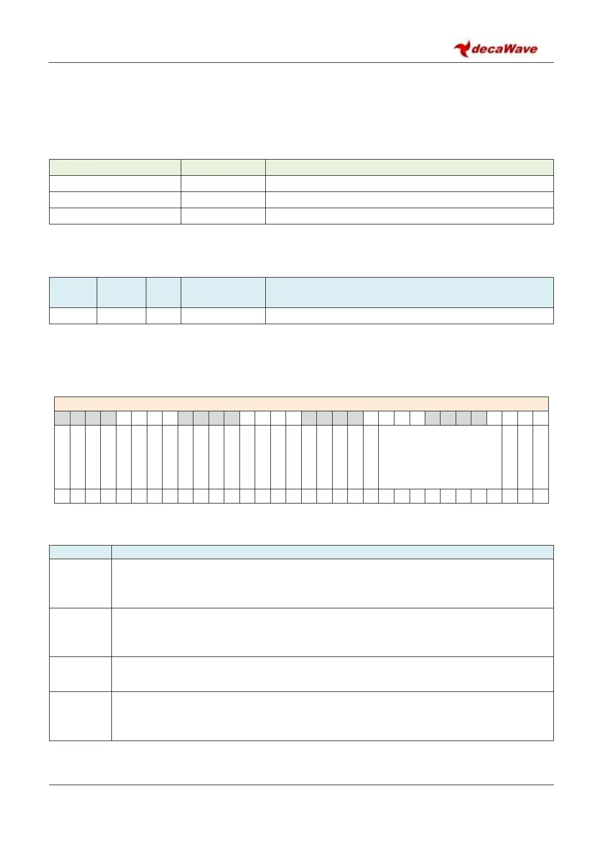
REG:24:00 –EC_CTRL– External clock synchronisation counter configuration
The fields of the EC_CTRL register identified above are individually described below:
Description of fields within Sub-Register 0x24:00 EC_CTRL
External transmit synchronisation mode enable. See section 6.1.2 – One Shot Transmit
Synchronisation (OSTS) Mode.
External receive synchronisation mode enable. See section 6.1.3 – One Shot Receive
Synchronisation (OSRS) Mode.
Clock PLL lock detect tune. This bit should be set to 1 to ensure reliable operation of the clock
PLL lock detect flags.
Wait counter used for external transmit synchronisation and external timebase reset. See
sections 6.1.2 – One Shot Transmit Synchronisation (OSTS) Mode and 6.1.1 – One Shot
Timebase Reset (OSTR) Mode.
 Loading...