Description of fields within Sub-Register 0x26:10 – GPIO_IRQE
GPIO IRQ Enable for GPIO7 input. Value 1 = enable, 0 = disable.
GPIO IRQ Enable for GPIO8 input. Value 1 = enable, 0 = disable.
Bits marked ‘-’ are reserved and should be written as zero.
7.2.39.6 Sub-Register 0x26:14 – GPIO_ISEN
GPIO Interrupt Sense Selection
Register file: 0x26 – GPIO control and status, sub-register 0x14 is the GPIO interrupt sense selection register.
The GPIO_ISEN register acts to set the state/event that gives rise to a GPI interrupt. Assuming that the GPIO
is an input and that it is enabled as an interrupt via the GPIO_IRQE register, then the GPIO_IMODE register
selects whether the interrupt is level or edge sensitive, and this register GPIO_ISEN selects which level or
edge is the state/event that causes the interrupt. The GPIO_ISEN register contains a bit for each GPIO pin to
allow each to be individually configured. The bits are as follows:
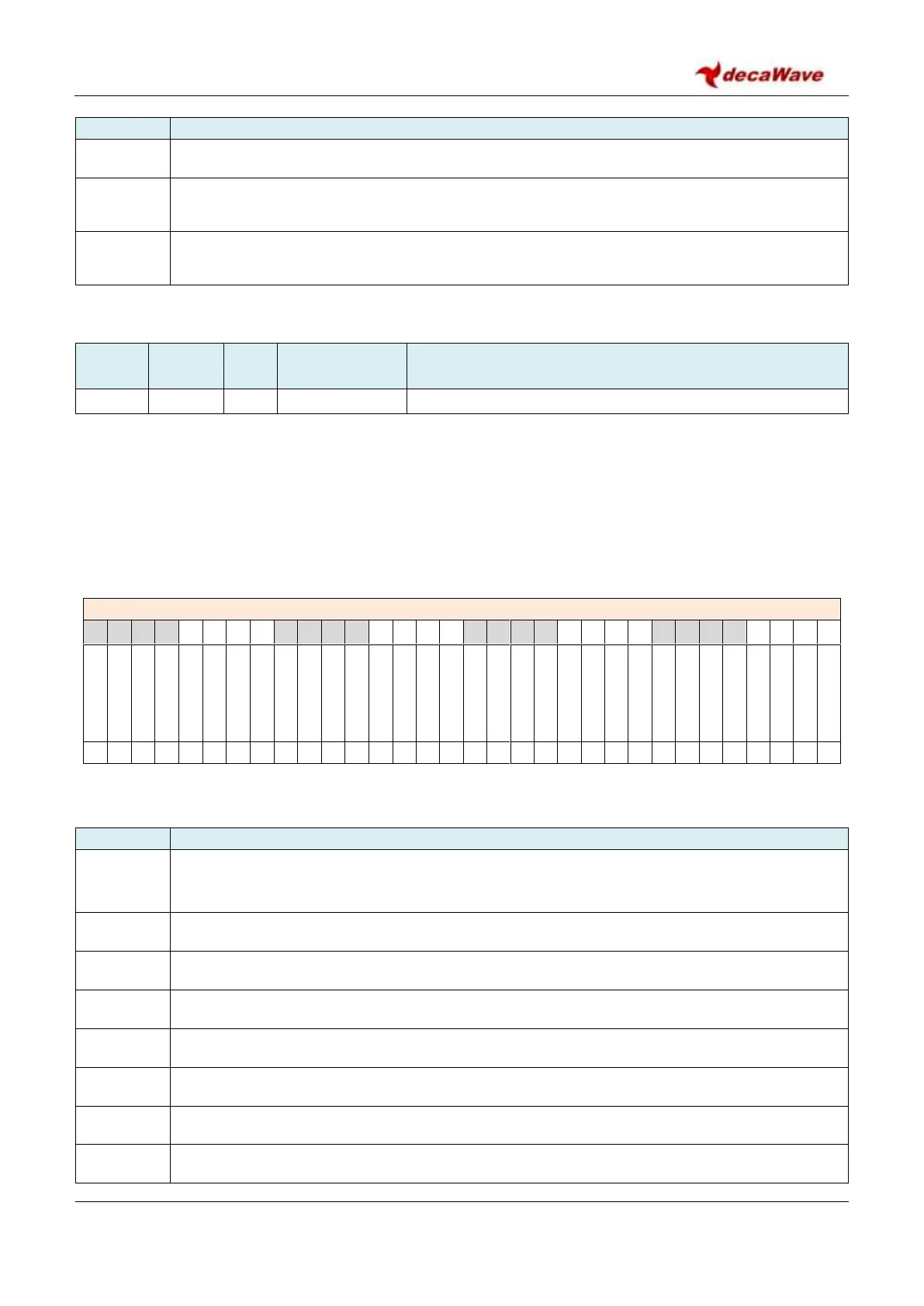
REG:26:14 – GPIO_ISEN – GPIO Interrupt Sense Selection register
The bits of the GPIO_ISEN register identified above are individually described below:
Description of fields within Sub-Register 0x26:14 – GPIO_ISEN
GPIO IRQ Sense selection GPIO0 input. Value 0 = Active high level sensitive interrupt or rising-
edge triggered interrupt. Value 1 = Active low level sensitive interrupt or falling-edge triggered
interrupt.
GPIO IRQ sense for GPIO1 input. Value 0 = High or Rising-Edge, 1 = Low or falling-edge.
GPIO IRQ sense for GPIO2 input. Value 0 = High or Rising-Edge, 1 = Low or falling-edge.
GPIO IRQ sense for GPIO3 input. Value 0 = High or Rising-Edge, 1 = Low or falling-edge.
GPIO IRQ sense for GPIO4 input. Value 0 = High or Rising-Edge, 1 = Low or falling-edge.
GPIO IRQ sense for GPIO5 input. Value 0 = High or Rising-Edge, 1 = Low or falling-edge.
GPIO IRQ sense for GPIO6 input. Value 0 = High or Rising-Edge, 1 = Low or falling-edge.
GPIO IRQ sense for GPIO7 input. Value 0 = High or Rising-Edge, 1 = Low or falling-edge.