Description of fields within Sub-Register 0x26:0C – GPIO_DOUT
Mask for setting the GPIO8 output state. (See GOM0).
7.2.39.5 Sub-Register 0x26:10 – GPIO_IRQE
Register file: 0x26 – GPIO control and status, sub-register 0x10 is the GPIO interrupt enable register. The
GPIO_IRQE register allows a GPIO input pin to be selected as an interrupt source into the DW1000.
Additional configuration registers GPIO_IMODE, GPIO_ISEN, GPIO_IBES and GPIO_IDBE allow the interrupt
to be set as level sensitive with control of whether it is the low or high state that generates the interrupt, or
as edge sensitive with control of the edge(s) that generates the interrupt, and includes a configurable de-
bounce circuit that can be used to ignore transients on the input. The GPIO_IRQE register contains a bit for
each GPIO pin to allow each to be individually selected as interrupt source. Setting the appropriate bit to 1
enables the corresponding GPIO input as an interrupt source, a value of 0 disables that interrupt. When a
GPIO interrupt is triggered it is signalled to the host via the GPIOIRQ event status bit in Register file: 0x0F –
System Event Status Register. The bits of the GPIO_IRQE register are as following:
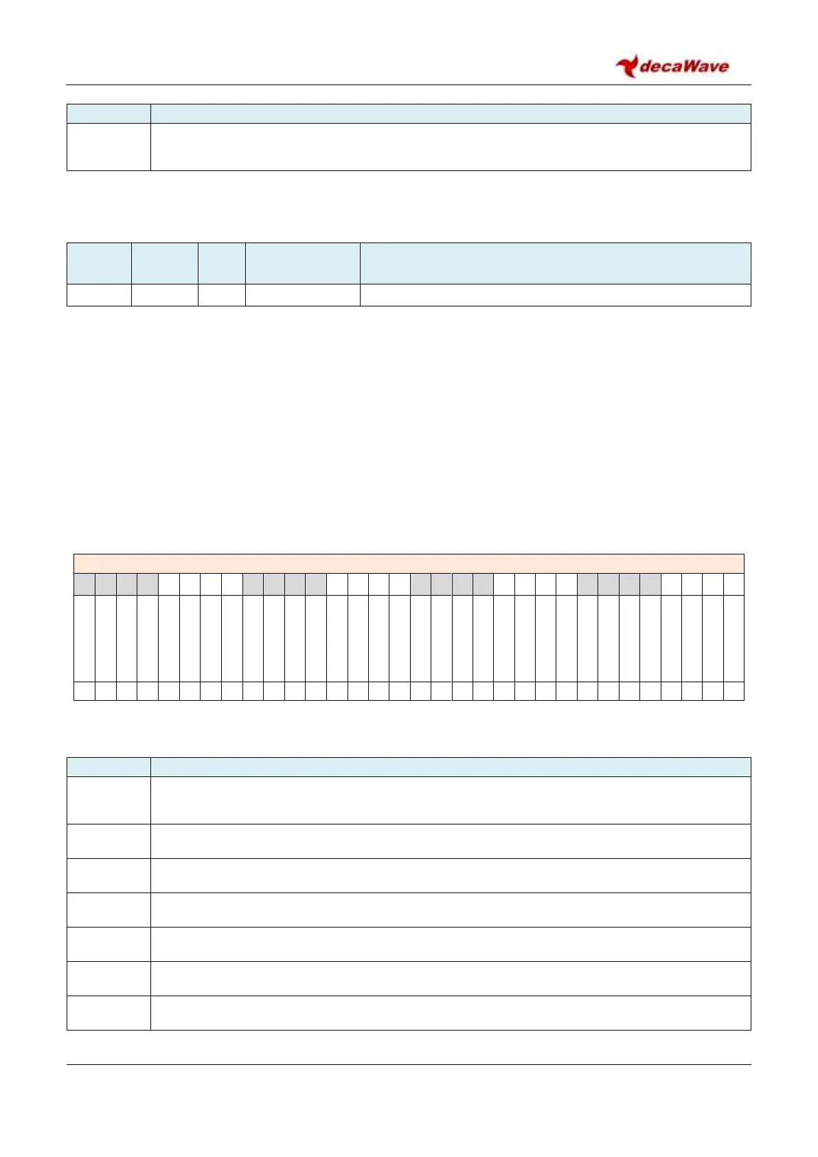
REG:26:10 – GPIO_IRQE – GPIO Interrupt Enable register
The bits identified above are individually described below:
Description of fields within Sub-Register 0x26:10 – GPIO_IRQE
GPIO IRQ Enable for GPIO0 input. Value 1 = enable GPIO input GPIO0 as an interrupt source.
Value 0 = GPIO0 is not an interrupt source.
GPIO IRQ Enable for GPIO1 input. Value 1 = enable, 0 = disable.
GPIO IRQ Enable for GPIO2 input. Value 1 = enable, 0 = disable.
GPIO IRQ Enable for GPIO3 input. Value 1 = enable, 0 = disable.
GPIO IRQ Enable for GPIO4 input. Value 1 = enable, 0 = disable.
GPIO IRQ Enable for GPIO5 input. Value 1 = enable, 0 = disable.
GPIO IRQ Enable for GPIO6 input. Value 1 = enable, 0 = disable.