Description of fields within Sub-Register 0x26:18 – GPIO_IMODE
GPIO IRQ Mode selection for GPIO8 input. Value 0 = Level, 1 = Edge.
Bits marked ‘-’ are reserved and should be written as zero.
7.2.39.8 Sub-Register 0x26:1C – GPIO_IBES
GPIO Interrupt “Both Edge” Select
Register file: 0x26 – GPIO control and status, sub-register 0x1C is the GPIO interrupt “Both Edge” selection
register. This only applies when edge sensitive interrupts are enabled in the GPIO_IMODE register. In this
case the GPIO_ISEN register normally acts to select which edge triggers the interrupt. This GPIO_IBES
register overrides the GPIO_ISEN register to select both edges as which edge triggers the interrupt. The
GPIO_IBES register contains a bit for each GPIO pin to allow each to be individually configured. The bits are
as follows:
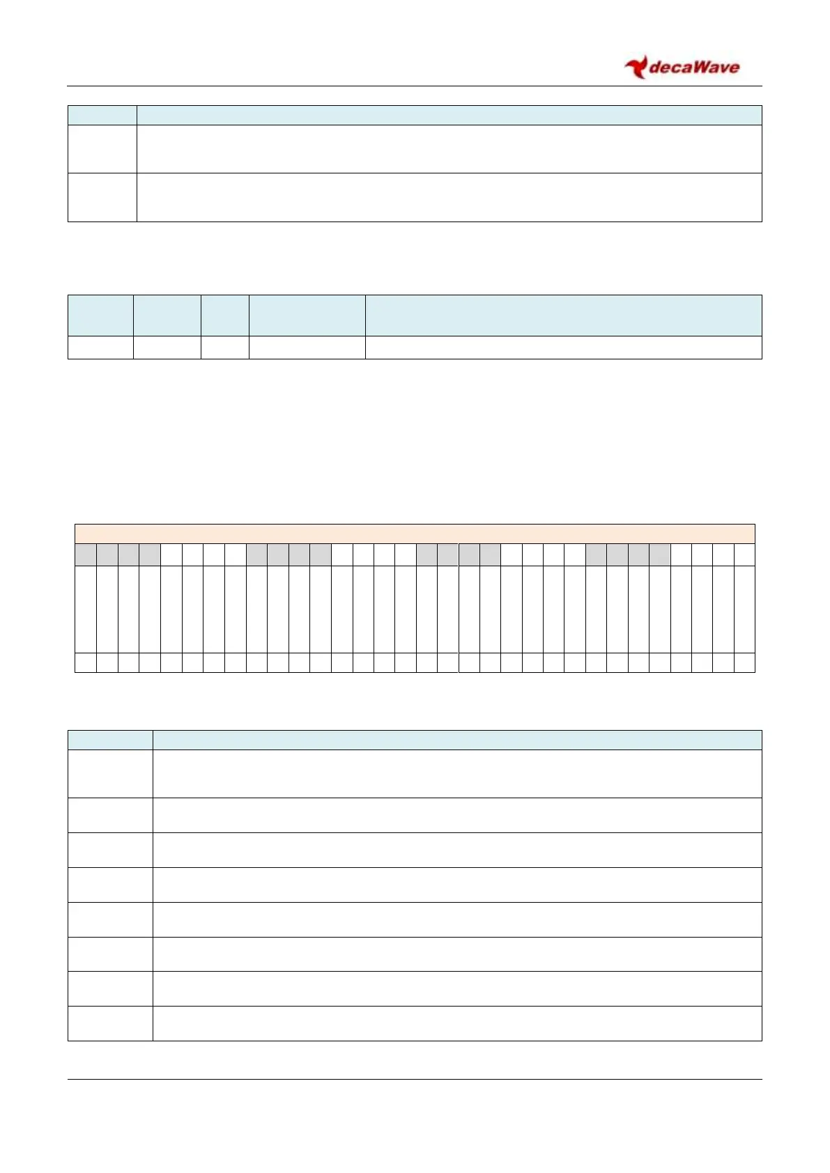
REG:26:1C – GPIO_IBES – GPIO Interrupt “Both Edge” selection register
The bits of the GPIO_IBES register identified above are individually described below:
Description of fields within Sub-Register 0x26:1C – GPIO_IBES
GPIO IRQ “Both Edge” selection for GPIO0 input. Value 0 = GPIO_IMODE register selects the
edge. Value 1 = Both edges trigger the interrupt.
GPIO IRQ “Both Edge” selection for GPIO1 input. Value 0 = use GPIO_IMODE, 1 = Both Edges.
GPIO IRQ “Both Edge” selection for GPIO2 input. Value 0 = use GPIO_IMODE, 1 = Both Edges.
GPIO IRQ “Both Edge” selection for GPIO3 input. Value 0 = use GPIO_IMODE, 1 = Both Edges.
GPIO IRQ “Both Edge” selection for GPIO4 input. Value 0 = use GPIO_IMODE, 1 = Both Edges.
GPIO IRQ “Both Edge” selection for GPIO5 input. Value 0 = use GPIO_IMODE, 1 = Both Edges.
GPIO IRQ “Both Edge” selection for GPIO6 input. Value 0 = use GPIO_IMODE, 1 = Both Edges.
GPIO IRQ “Both Edge” selection for GPIO7 input. Value 0 = use GPIO_IMODE, 1 = Both Edges.