Description of fields within Sub-Register 0x26:1C – GPIO_IBES
GPIO IRQ “Both Edge” selection for GPIO8 input. Value 0 = use GPIO_IMODE, 1 = Both Edges.
Bits marked ‘-’ are reserved and should be written as zero.
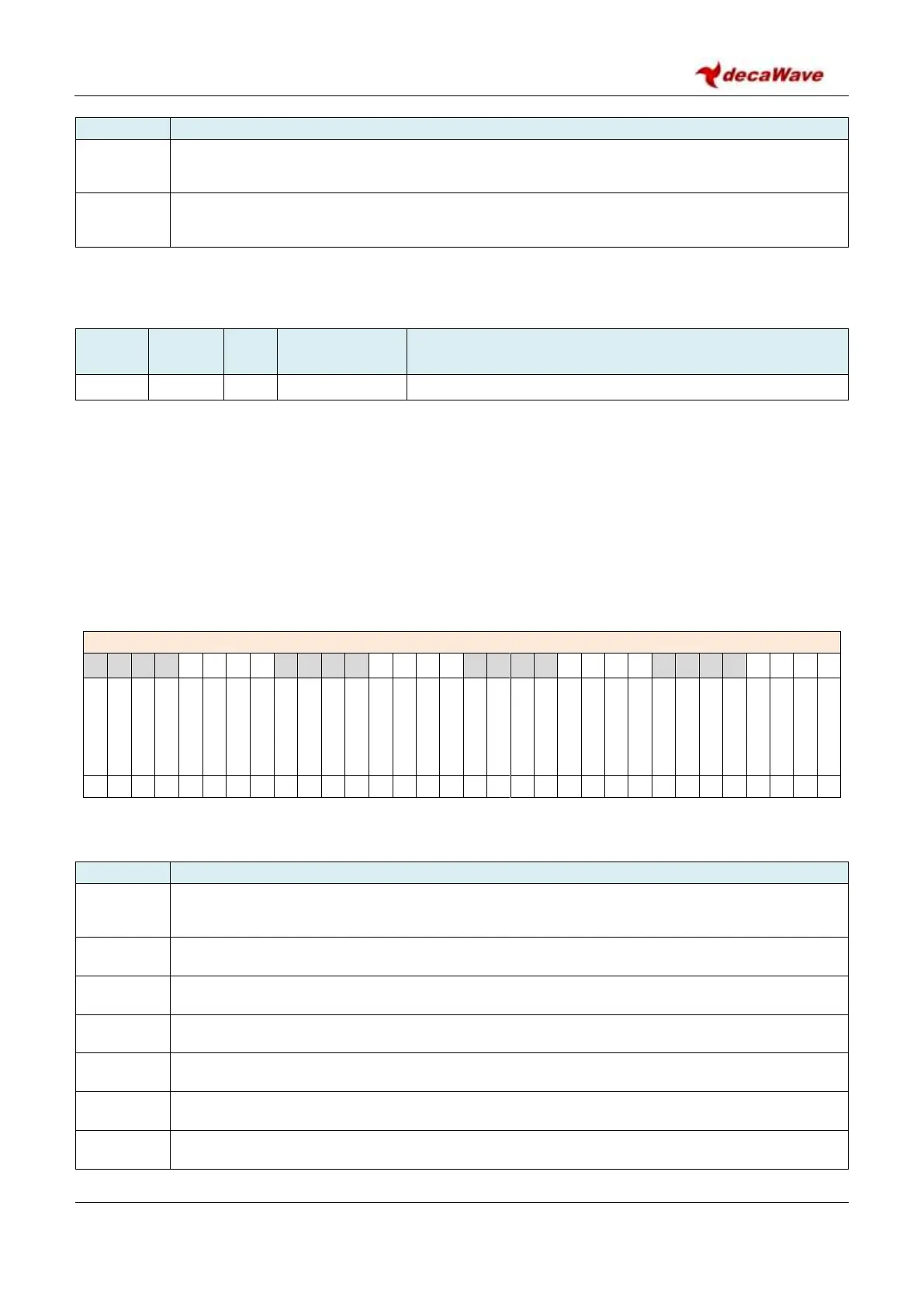
7.2.39.9 Sub-Register 0x26:20 – GPIO_ICLR
GPIO Interrupt Latch Clear
Register file: 0x26 – GPIO control and status, sub-register 0x20 is the GPIO interrupt clear register. When a
GPIO interrupt occurs that meets the configured criteria (edge/level etc.) that event is latched in an internal
interrupt latch. To clear the interrupt the host needs to write a 1 to the appropriate bit of this GPIO_ICLR
register. There is no way to read the interrupt latch, which means that only one GPIO can be enabled to
interrupt at a time, unless the host has some other external way to distinguish events. Although level
sensitive interrupts are latched, if the active level persists, then clearing the latch will be ineffective, since
the interrupt will occur again immediately. The GPIO_ICLR register contains a bit for each GPIO pin as
follows:
REG:26:20 – GPIO_ICLR – GPIO Interrupt latch clear
The bits of the GPIO_ICLR register identified above are individually described below:
Description of fields within Sub-Register 0x26:20 – GPIO_ICLR
GPIO IRQ latch clear for GPIO0 input. Write 1 to clear the GPIO0 interrupt latch. Writing 0 has
no effect. Reading returns zero.
GPIO IRQ latch clear for GPIO1 input. Write 1 to clear the interrupt latch.
GPIO IRQ latch clear for GPIO2 input. Write 1 to clear the interrupt latch.
GPIO IRQ latch clear for GPIO3 input. Write 1 to clear the interrupt latch.
GPIO IRQ latch clear for GPIO4 input. Write 1 to clear the interrupt latch.
GPIO IRQ latch clear for GPIO5 input. Write 1 to clear the interrupt latch.
GPIO IRQ latch clear for GPIO6 input. Write 1 to clear the interrupt latch.