EasyManua.ls Logo

decaWave DW1000 - Page 143

decaWave DW1000
242 pages
Print Icon
To Next Page IconTo Next Page
To Previous Page IconTo Previous Page
Loading...
DW1000 User Manual
© Decawave Ltd 2017
Version 2.12
Page 143 of 242
Field
Description of fields within Sub-Register 0x26:24 GPIO_IDBE
GIDBE6
bit:6
GPIO6 IRQ de-bounce configuration. Value 1 = de-bounce enabled, 0 = de-bounce disabled.
GIDBE7
bit:7
GPIO7 IRQ de-bounce configuration. Value 1 = de-bounce enabled, 0 = de-bounce disabled.
GIDBE8
reg:26:24
bit:8
GPIO8 IRQ de-bounce configuration. Value 1 = de-bounce enabled, 0 = de-bounce disabled.
-
reg:26:24
bits:319
Bits marked ‘-’ are reserved and should be written as zero.
7.2.39.11 Sub-Register 0x26:28 GPIO_RAW
ID
Length
(octets)
Type
Mnemonic
Description
26:28
4
RO
GPIO_RAW
GPIO raw state
Register file: 0x26 GPIO control and status, sub-register 0x28 allows the raw state of the GPIO pin to be
read. The GPIO_RAW register contains a bit for each GPIO pin as follows:
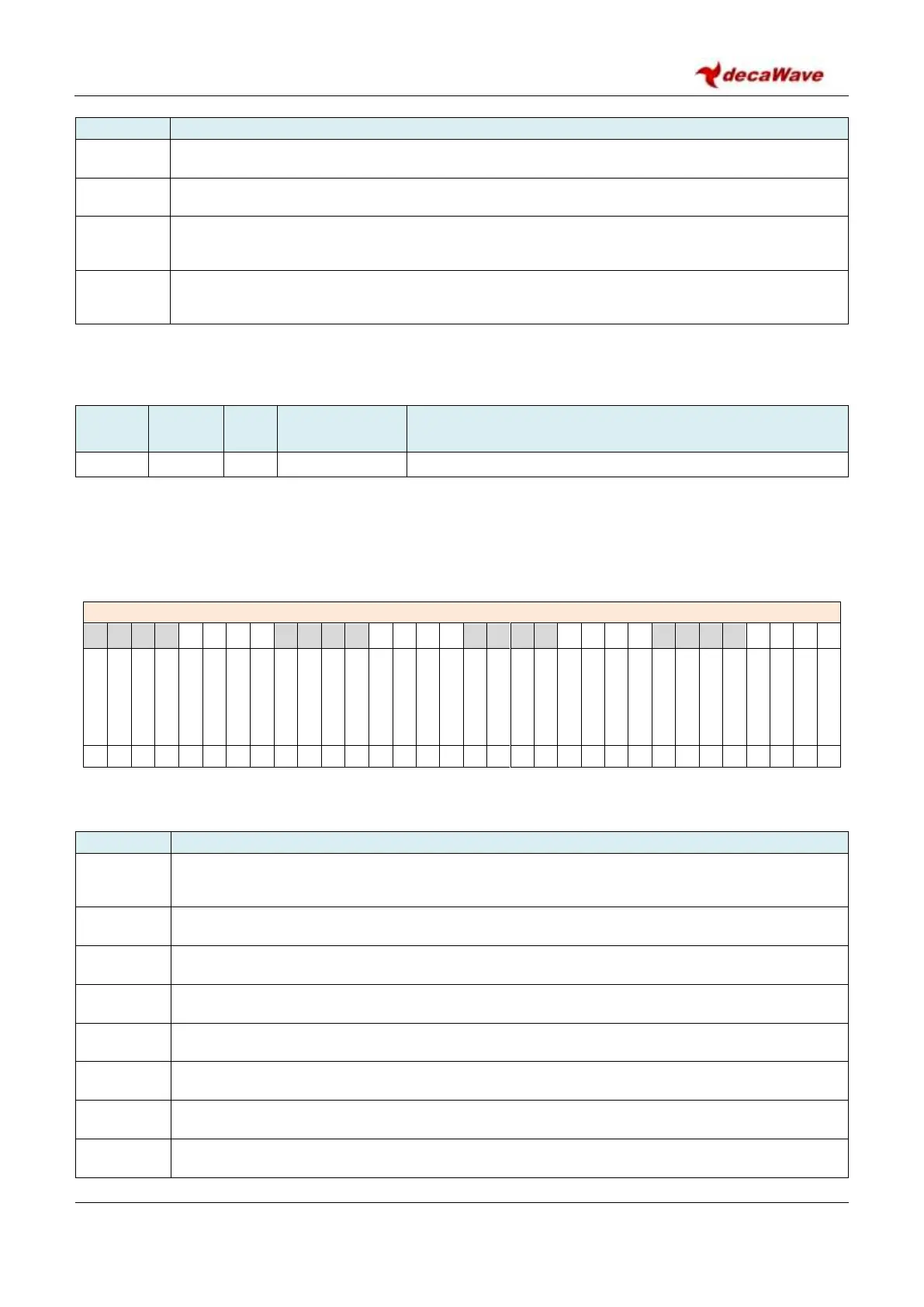
REG:26:28 GPIO_RAW GPIO raw state
31
30
29
28
27
26
25
24
23
22
21
20
19
18
17
16
15
14
13
12
11
10
9
8
7
6
5
4
3
2
1
0
-
-
-
-
-
-
-
-
-
-
-
-
-
-
-
-
-
-
-
-
-
-
-
GRAWP8
GRAWP7
GRAWP6
GRAWP5
GRAWP4
GRAWP3
GRAWP2
GRAWP1
GRAWP0
-
-
-
-
-
-
-
-
-
-
-
-
-
-
-
-
-
-
-
-
-
-
-
0
0
0
0
0
0
0
0
0
The bits of the GPIO_RAW register identified above are individually described below:
Field
Description of fields within Sub-Register 0x26:28 GPIO_RAW
GRAWP0
reg:26:28
bit:0
This bit reflects the raw state of GPIO0.
GRAWP1
bit:1
GPIO1 port raw state.
GRAWP2
bit:2
GPIO2 port raw state.
GRAWP3
bit:3
GPIO3 port raw state.
GRAWP4
bit:4
GPIO4 port raw state.
GRAWP5
bit:5
GPIO5 port raw state.
GRAWP6
bit:6
GPIO6 port raw state.
GRAWP7
bit:7
GPIO7 port raw state.

Table of Contents