Definition of the bit fields within Sub-Register 0x2A:00 – TC_SARC:
Description of fields within Sub-Register 0x2A:00 – TC_SARC
Writing 1 sets SAR enable and writing 0 clears the enable. The enable should set for a
minimum of 2.5 µs to allow the SAR time to complete its reading.
Bits marked ‘-’ in register 0x2A:00 are reserved and should always be written as zero to
avoid any malfunction of the DW1000.
7.2.43.2 Sub-Register 0x2A:03 – TC_SARL
Transmitter Calibration –Latest SAR readings
Register file: 0x2A – Transmitter Calibration block, sub-register 0x03, contains the following bitmapped sub-
fields:
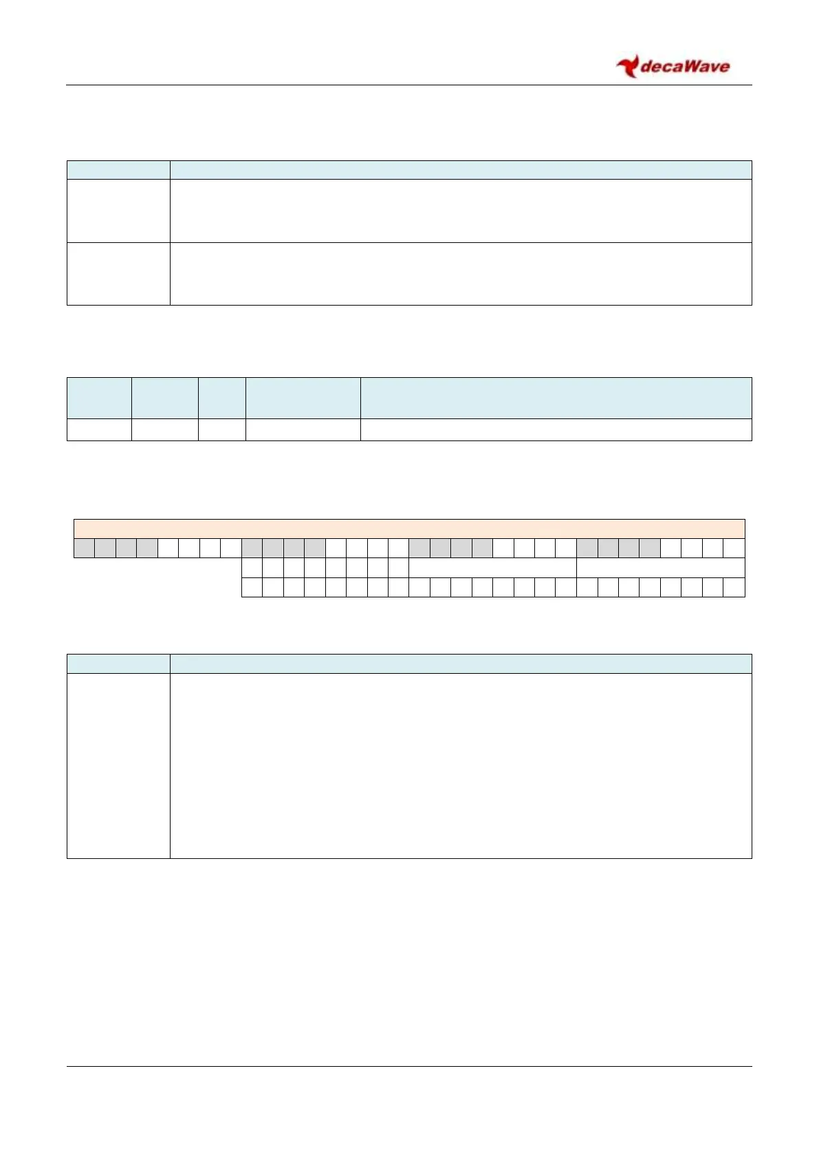
REG:2A:03 – TC_SARL – Transmitter Calibration Latest SAR readings
Definition of the bit fields within Sub-Register 0x2A:03 – TC_SARL:
Description of fields within Sub-Register 0x2A:03 – TC_SARL
SAR_LVBAT
reg:2A:03
bits:7–0
Latest SAR reading for Voltage level. The 8-bit value reported here is the voltage reading,
from the last time the SAR A/D was used to sample the battery voltage monitor output. The
LSB is approximately 6 mV. The value can be converted to an actual voltage by employing
the formula:
Voltage (volts) = ( (SAR_LVBAT – OTP_READ(V
meas
@ 3.3 V) ) / 173) + 3.3
This uses the stored 3.3 V reading in the OTP that was recorded during production test.
The effective range of measurement is 2.25 V to 3.76 V. For more details please refer to
For more details please refer to section 6.4 – Measuring IC temperature and voltage.
 Loading...