Register file: 0x2E – Leading Edge Detection Interface, sub-register 0x0000 is a 16-bit status register
reporting the threshold that was used to find the first path. This threshold is calculated based on an
estimate of the noise made during the LDE algorithm’s analysis of the accumulator data. This threshold
report may be of diagnostic interest in certain circumstances.
7.2.47.2 Sub-Register 0x2E:0806 – LDE_CFG1
LDE Configuration Register 1
Register file: 0x2E – Leading Edge Detection Interface, sub-register 0x0806 is an8-bit configuration register
containing the following fields:
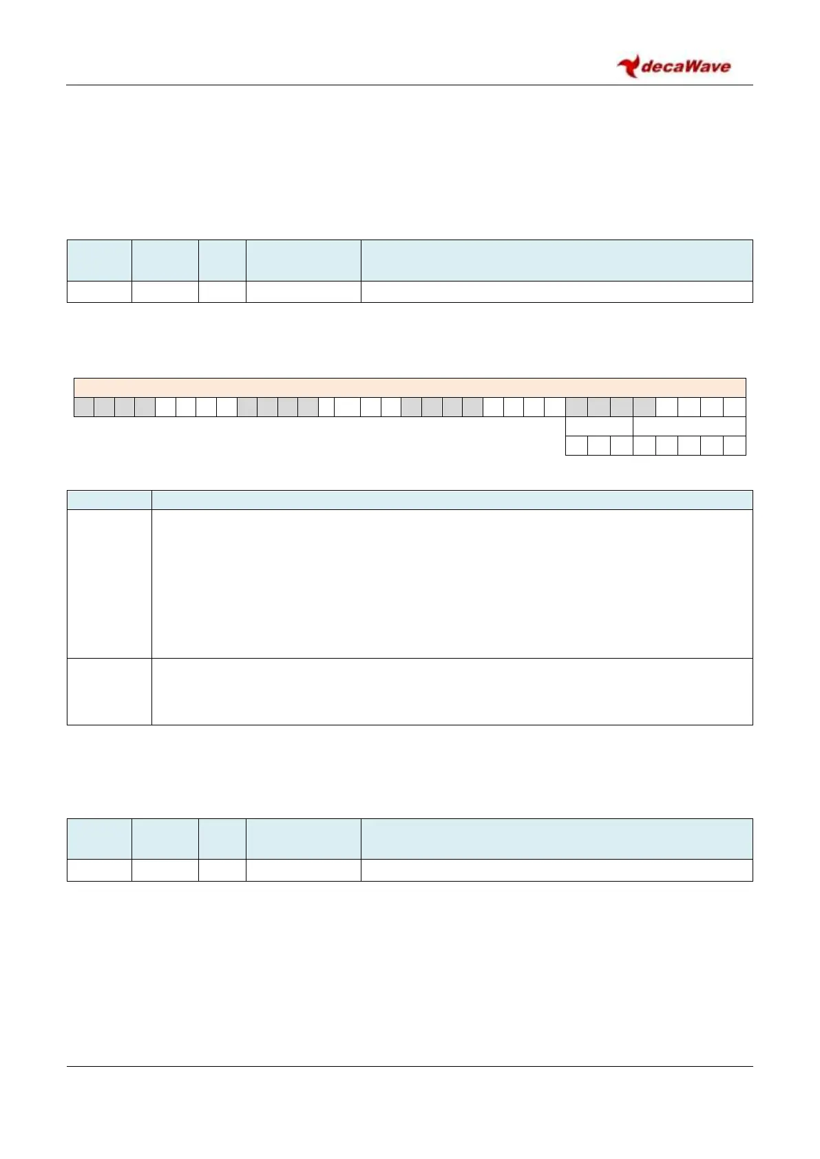
REG:2E:0806 – LDE_CFG1 – LDE Configuration Register 1
The fields of the LDE_CFG1register are described below:
Description of fields within Sub-Register 0x2E:0806 – LDE_CFG1
Noise Threshold Multiplier. This is a factor by which the observed noise level is multiplied to
set the threshold for the LDE algorithm’s first path search. By default NTM is 12. This value
was found to work well and give a reasonable compromise performance level between falsely
triggering on noise peaks and missing real attenuated (non-line-of-sight) first paths. More
recently an NTM value of 13 has been used in our device driver software to give more accuracy
in close-up LOS conditions. Where NLOS performance is more important to the application the
default NTM value of 12 might be a better choice. Refer to the application notes available on
www.Decawave.com for more information.
PMULT
reg:2E:0806
bits:7–5
Peak Multiplier. This sets a factor by which the peak value of estimated noise is increased in
order to set the threshold for first path searching. By default this value is 3, giving a factor of
1.5, which has been found to work well.
NB: To avoid any malfunction please ensure to only write one octet into the LDE_CFG1 register.
7.2.47.3 Sub-Register 0x2E:1000 – LDE_PPINDX
Register file: 0x2E – Leading Edge Detection Interface, sub-register 0x1000, is the LDE Peak Path Index
(LDE_PPINDX) register. This is a 16-bit status register reporting the position within the accumulator that the
LDE algorithm has determined to contain the maximum magnitude path. This value is set during the LDE
algorithm’s analysis of the accumulator data. This value may be of diagnostic interest in certain
circumstances. The magnitude of the value at this index is reported in Sub-Register 0x2E:1002 –
LDE_PPAMPL.