performance optimization again comes at a cost, which is that the total crystal offset
between transmitter and receiver must be kept very tight, at or below about 1 ppm. This
might be done, for example, by using very high quality 0.5 ppm TCXOs in both the
transmitter and the receiver. The Tight operating parameter can only be selected via direct
host load control using the OPS_KICK and OPS_SEL controls in Sub-Register 0x2D:08 –
OTP_STAT.
For most applications the default operating parameter set is the best choice. The use of the other operating
parameter sets may improve performance in particular use cases, but requires tighter control of clock
frequencies across the network of devices that have to interwork.
7.2.47 Register file: 0x2E – Leading Edge Detection Interface
Leading Edge Detection Interface
Register map register file 0x2E is the LDE control/status interface. The Leading Edge detection function is
responsible for analysing the accumulator data, (available in Register file: 0x25 – Accumulator CIR memory),
to find the first path and calculate the RX timestamp written to Register file: 0x15 – Receive Time Stamp and
the diagnostic information written into Register file: 0x12 – Rx Frame Quality Information. The LDE interface
contains a number of sub-registers. An overview of these sub-registers is given by Table 49 and each is then
separately described in the sub-sections below.
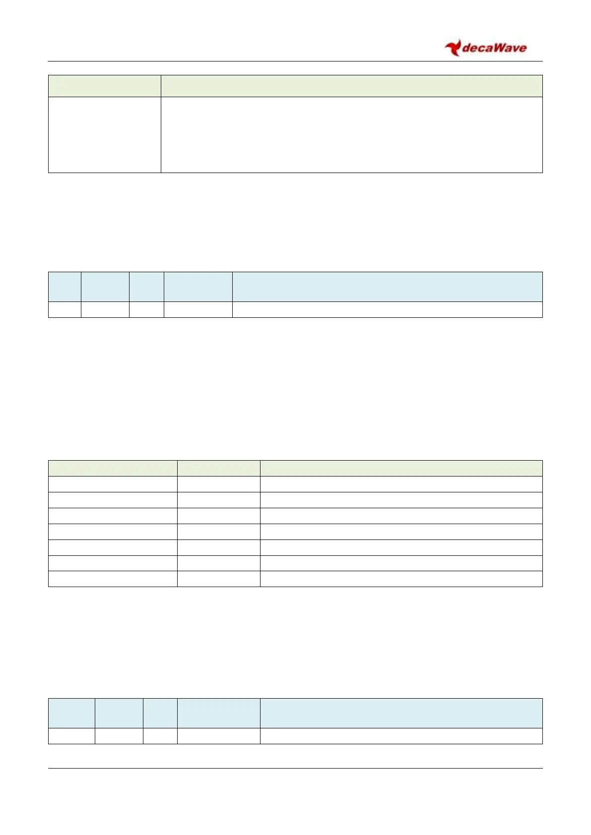
Table 49: Register file: 0x2E – Leading Edge Detection Interface overview
LDE Configuration Register 1
LDE Receive Antenna Delay configuration
LDE Configuration Register 2
LDE Replica Coefficient configuration
PLEASE NOTE: Other areas within the address space of Register file: 0x2E – Leading Edge Detection Interface
are reserved. To ensure proper operation of the LDE algorithm (i.e. to avoid loss of performance or a
malfunction), care must be taken not to write to any byte locations other than those defined in the sub-
sections below.
7.2.47.1 Sub-Register 0x2E:0000 – LDE_THRESH
 Loading...