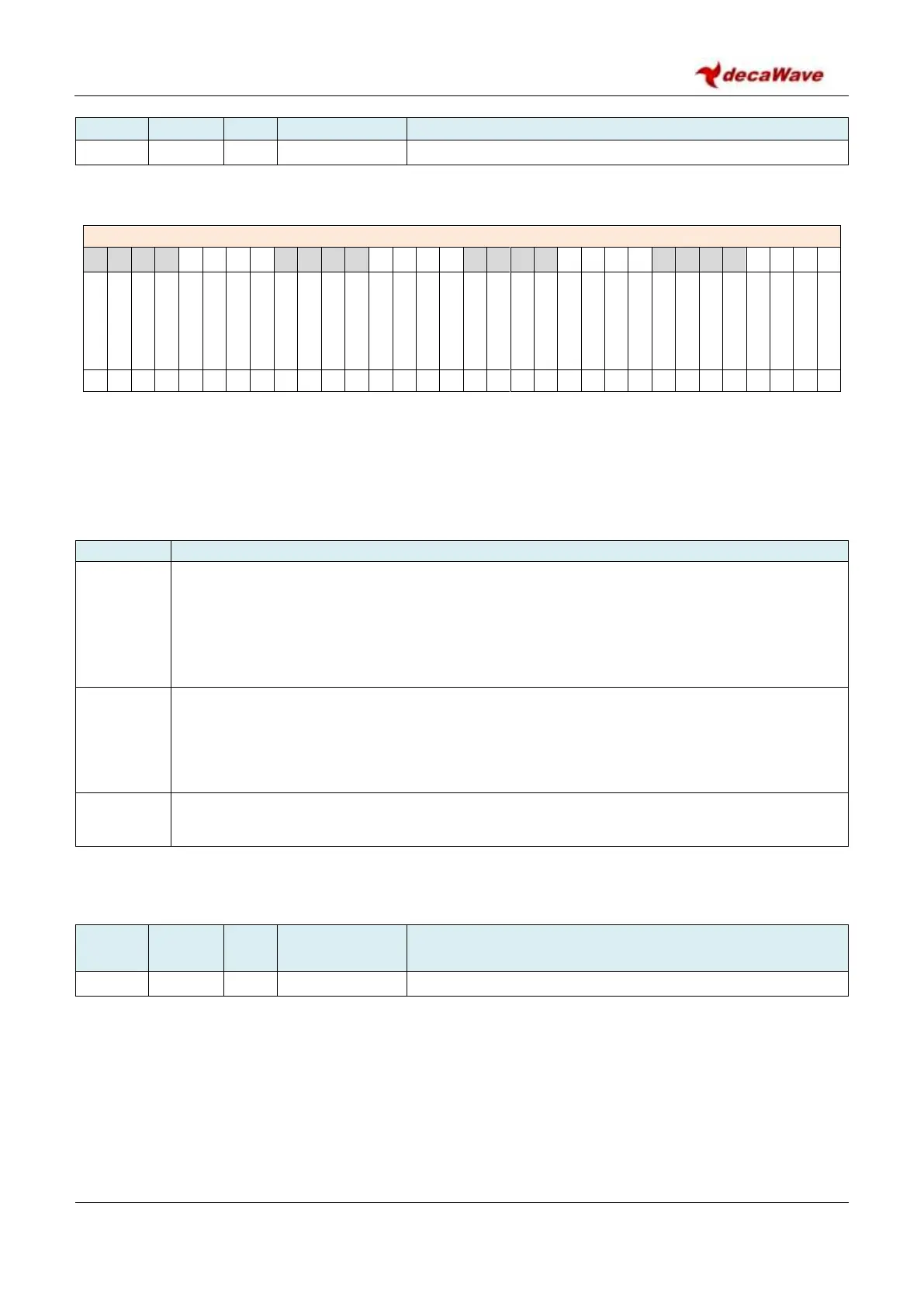
Register file: 0x2F – Digital Diagnostics Interface, sub-register 0x00 is the event counter control register.
REG:2F:00 – EVC_CTRL – Event Counter Control
Fields in the EVC_CTRL register are intended to be self-clearing. So, the event counters can be enabled or
cleared, but cannot be disabled. The register expects a two-byte minimum length write to the lowest two
bytes of the register. If a one-byte write is made to this register, the bits will not clear as expected.
The bits of the EVC_CTRL register identified above are individually described below:
Description of fields within Sub-Register 0x2F:00 – Event Counter Control
Event Counters Enable. The EVC_EN bit acts to enable the event counters. When EVC_EN bit
is zero none of the event counters will update. When EVC_EN bit is set to 1 it enables event
counting. A number of sub-registers of Register file: 0x2F – Digital Diagnostics Interface,
contain counters of various system events – see below for the detailed description of the
parameters counted. If the host system has no interest in these event counters then a small
amount of power is saved by not enabling event counting.
Event Counters Clear. The EVC_CLR bit acts to clear event counters to zero. This cannot be
done while EVC_EN bit is set. The correct procedure to clear the event counters is to write
0x02 to Sub-Register 0x2F:00 – Event Counter Control to disable counting and clear the counter
values to zero, and then to write 0x01 to Sub-Register 0x2F:00 – Event Counter Control to re-
enable counting if required.
The remaining bits of Sub-Register 0x2F:00 – Event Counter Control are reserved and should
always be set to zero to avoid any malfunction of the device.
7.2.48.2 Sub-Register 0x2F:04 – PHR Error Counter
Register file: 0x2F – Digital Diagnostics Interface, sub-register 0x04is the PHY Header Error event counter.


 To Next Page